SERVICE INFORMATION :
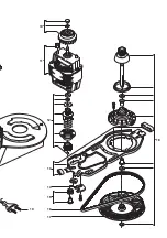
- The blender coupling on the motor shaft has been provided
with a customary left-handed thread.
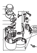
The drive coupling (item 10) can be detached by means of
a hammer and a screwdriver. Strike the screwdriver with a
short sharp blow and remove the drive coupling, or block
the acc. drive wheel (item 17) and thereby the rotor shaft,
by sticking a pin through the hole (5 mm dia. – marked with
an arrow) in the bottom plate.
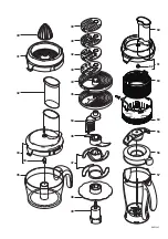
- The assembly of the accessories depends on the national
version.
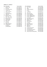
- For specifi c versions, the component confi guration may
differ from the one shown on the exploded view. However,
the actual components can be distinguished by their code
numbers.
- Make sure that all functions, including the safety devices,
are working correctly after you have completed the repair.
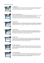
- To check the processes of smart control, please look at the
described functions on the next page.
Automatic resettable cut-out
(part of item 11)
To prevent damage due to overheating, the appliance has
been equipped with an automatic cut-out system.
This system will automatically cut off the power supply when
the appliance overheats.
If the appliance suddenly stops running:
- Unplug the appliance
- Switch off the appliance
- Let the appliance cool down for 15 minutes
- Plug the appliance in again
- Switch the appliance on again
Safety lock
(item 7)
Place the lid on the bowl in the right position. The appliance
will only function if the line on the applinace is directly
opposite the mark on the lid of the food processor bowl and
the same holds for the other accessoires. The built-in safety
lock will now be deblocked and you can turn the appliance on.
Note that if both the blender jar and the bowl have been
correctly mounted, only the blender will function.
Important:
If the appliance is used without the blender jar, the appliance
will not function, when the blender coupling (item 10) has not
been protected by the blender cover (item 1).
Note:
The blender cover can only be removed, when the bowl
including the bowl lid is not mounted on the foodprocessor.
How to set the belt tension:
Step 1: Give 30 N pretension force on the adjusting plate to
minimise the distances between the belt and the belt
wheels
Step 2: Reduce the tension force from 30 N down to 10 N
which is the required belt drive force for the appliance.
Step 3: Fix the adjusting screw on the adjusting plate when
the tension force reaches the value of 10 N (after
coming down from 30 N!)
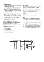
MAINS
C1
Change-over switch
in braking position
Main PCB
brown
red
yellow
white
red
S1
S2
black
yellow
F1
F2
Rotor
R10
U


