Electrical Alignments
EN 82
F21RE AB
8.
5.
If the frequency lies outside this range, adjust the
frequency in the FINE TUNE line to 475.25 MHz and
STORE the program (this is very important because this
will disable the AFC algorithm).
6.
Navigate to the SAM main menu and select ALIGNMENTS
- GENERAL - IF AFC.
7.
During the IF AFC parameter adjustment, there is OSD
feedback at the top of the screen.
8.
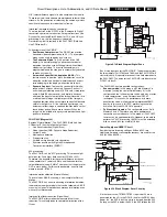
This OSD feedback will contain one of four messages:
Table 8-1 AFC Alignment feedback
The first item (IN or OUT) informs you whether you are in or out
of the AFC window. The second item (HIGH or LOW) informs
you whether the AFC frequency is too high or too low.
1.
Adjust the IF AFC parameter until the first value is within
the AFC window (= IN).
2.
Next, adjust the IF AFC parameter until the second value is
LOW.
3.
After adjustment, STORE the value.
4.
Return to the INSTALL menu.
5.
Select MANUAL INSTALLATION - SEARCH - 475.00 - OK
and STORE. This will turn the AFC algorithm ON again.
Service tip: If you do not trust the frequency accuracy of your
service generator, connect it to a "good" TV set and check it
with the FINE TUNE line.
IF LPRIMEAFC
Same procedure as described above but with other signal
source (SECAM L').
TUNER AGC
Connect the RF output of a video pattern generator to the
antenna input.
From the generator, supply an PAL B/G TV signal with a signal
strength of approximately 2 mV and a frequency of 475.25
MHz.
Measure the DC voltage on pin 1 of the Tuner (item 1102). You
can adjust this voltage by adjusting the TUNER AGC item in the
SAM menu. Alignment is correct when the DC voltage is just
below 3.8 V.
BLEND INTENSITY
This adjustment aligns the level of transparency of the menu
display that is blended into the main display. Use this alignment
when the main microprocessor or the HOP IC is replaced.
1.
Set the BRIGHTNESS, CONTRAST, and COLOR values
(in the PICTURE menu) at the midpoint.
2.
Using a video pattern generator, apply a signal with a
100% white video pattern to the set.
3.
Connect an oscilloscope to the “Red” output of the
Receiver box (pin 1 of the MONITOR OUT sub-D
connector) and measure the Red output level.
4.
Align the BLEND INTENSITY parameter so that the
blended signal is 65 % of the black/white amplitude. This
ratio will be about 0.45 V (blended signal) to 0.7 V (full
white signal).
FBX TEST PATTERN
When this pattern is switched on, the set will display a picture
that slowly changes from black to white, and vice versa. Use
this pattern to check the functionality of the circuitry behind the
FBX and the FBX function itself.
You can also use this pattern as a picture generator for the Flat
TV plasma monitor (for example, for checking cell defects,
interpretation of the ADC/DAC converters, etc).
Important: Be sure to set this pattern to OFF again when it is
no longer needed, since it will not be automatically disabled
when SAM is exited.
8.3.2
DRIVE Alignments
TEST PATTERN
The TEST PATTERN is not really needed for the alignment of
the Receiver box. It can be used in the TV configuration as a
test pattern to align the white colour temperatures of the
monitor. However, the monitor itself (as a stand alone unit) can
also be aligned in other ways (described in the Service Manual
of the TV monitor).
RGB Output Amplitude Adjustment
1.
Load the RGB output (sub-D connector AV303) of the
Receiver box with a TV monitor (or match RGB output lines
with 75 ohm resistors, if no monitor is available), and
measure the outputs with an oscilloscope.
2.
Apply an artificial white CVBS signal (1 V_pp white-to-top-
sync, with a 0.3 V sync amplitude) to the external 2 input.
3.
Set LUMA GAIN to a value of "3" (via the SAM menu
ALIGNMENTS - GENERAL).
4.
Set RED, GREEN, and BLUE to "24" (via the SAM menu
ALIGNMENTS - DRIVE).
5.
Set RED BL OFFSET and GREEN BL OFFSET to "7".
6.
Adjust the gain (with the RED, GREEN, and BLUE slider
bars) until the oscilloscope-measured values for R, G, and
B are 700 mV
±
10 mV with respect to the front porch of the
signal.
8.3.3
LUM. DELAY Alignments
With this alignment, you place the luminance information
directly on the chrominance information (brightness is pushed
onto the colour). Input a colour bar or grey scale pattern as a
test signal.
LUM. DELAY PAL BG
Set value to "12". If the luminance signal referred to the
chrominance signal still has a time delay, adjust the value to
solve this.
LUM. DELAY PAL I
Set value to "12". If the luminance signal referred to the
chrominance signal still has a time delay, adjust the value to
solve this.
LUM. DELAY SECAM
Set value to "11". If the luminance signal referred to the
chrominance signal still has a time delay, adjust the value to
solve this.
LUM. DELAY BYPASS
Set value to "10". If the luminance signal referred to the
chrominance signal still has a time delay, adjust the value to
solve this.
AFC-window
AFC-frequency versus reference
Out
High
In
High
*In*
*Low*
Out
Low
Summary of Contents for F21RE
Page 7: ...Directions for Use EN 7 F21RE AB 3 3 Directions for Use ...
Page 8: ...Directions for Use EN 8 F21RE AB 3 ...
Page 9: ...Directions for Use EN 9 F21RE AB 3 ...
Page 10: ...Directions for Use EN 10 F21RE AB 3 ...
Page 11: ...Directions for Use EN 11 F21RE AB 3 ...
Page 12: ...Directions for Use EN 12 F21RE AB 3 ...
Page 13: ...Directions for Use EN 13 F21RE AB 3 ...
Page 14: ...Directions for Use EN 14 F21RE AB 3 ...
Page 15: ...Directions for Use EN 15 F21RE AB 3 ...
Page 16: ...Directions for Use EN 16 F21RE AB 3 ...
Page 17: ...Directions for Use EN 17 F21RE AB 3 ...
Page 18: ...Directions for Use EN 18 F21RE AB 3 ...
Page 19: ...Directions for Use EN 19 F21RE AB 3 ...
Page 20: ...Directions for Use EN 20 F21RE AB 3 ...
Page 21: ...Directions for Use EN 21 F21RE AB 3 ...
Page 22: ...Directions for Use EN 22 F21RE AB 3 ...
Page 23: ...Directions for Use EN 23 F21RE AB 3 ...
Page 24: ...Directions for Use EN 24 F21RE AB 3 ...
Page 25: ......
Page 114: ...Revision List EN 114 F21RE AB 11 11 Revision List First release ...


