Circuit Descriptions, List of Abbreviations, and IC Data Sheets
EN 94
F21RE AB
9.
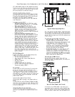
The OTC also has a connection with the Front panel:
•
Driving the "on" and "STANDBY" LEDs.
Service tip: The green LED gives a quick indication that
the 8V6 voltage is present.
•
This chassis has an IR send-LED connected to pin 90 for
communication with DST or ComPair.
•
The remote control signal comes in on pin 100.
Memory
The set software is in a 4 MB ROM (IC7002) and in a 32 KB
ROM inside the OTC. The level at pin 73 of the OTC
determines whether this internal software is used at start up.
This level is determined with R3026/3029. The external ROM
is driven via the OE and CS signals.
The Non Volatile Memory (NVM) IC7008 is a 32 KB version
M24C32W6, and is used to store
•
Software identification.
•
Operational hours.
•
Error codes.
•
Option codes.
•
Presets.
•
Alignments.
All ICs in this part are supplied with 3V3. For this, a 3V3
stabilizer is used (IC7009).
Monitor communication (UART/FSP)
In total, four versions of the Receiver box are realised. There is
an US and EU version (main difference is the HD part for US).
Furthermore, there will be version for the current 42" FTV1.9
monitor and a version for the new FM2x monitor range. The
difference between these versions is mainly the
communication between the Receiver box and monitor. See
table below:
Table 9-3 Overview UART diversity
The Receiver box has to support both the FTV1.9 and the
FM2x plasma monitors. The communication protocol for the
FTV1.9 monitor is based on UART with a CONFIG_IDENT
signal. However, all FM2x monitors have a new improved
protocol called FSP (FTV System Protocol). Therefore, the pin
layout on the FTV monitor output connector has been changed.
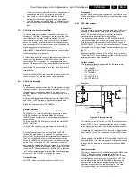
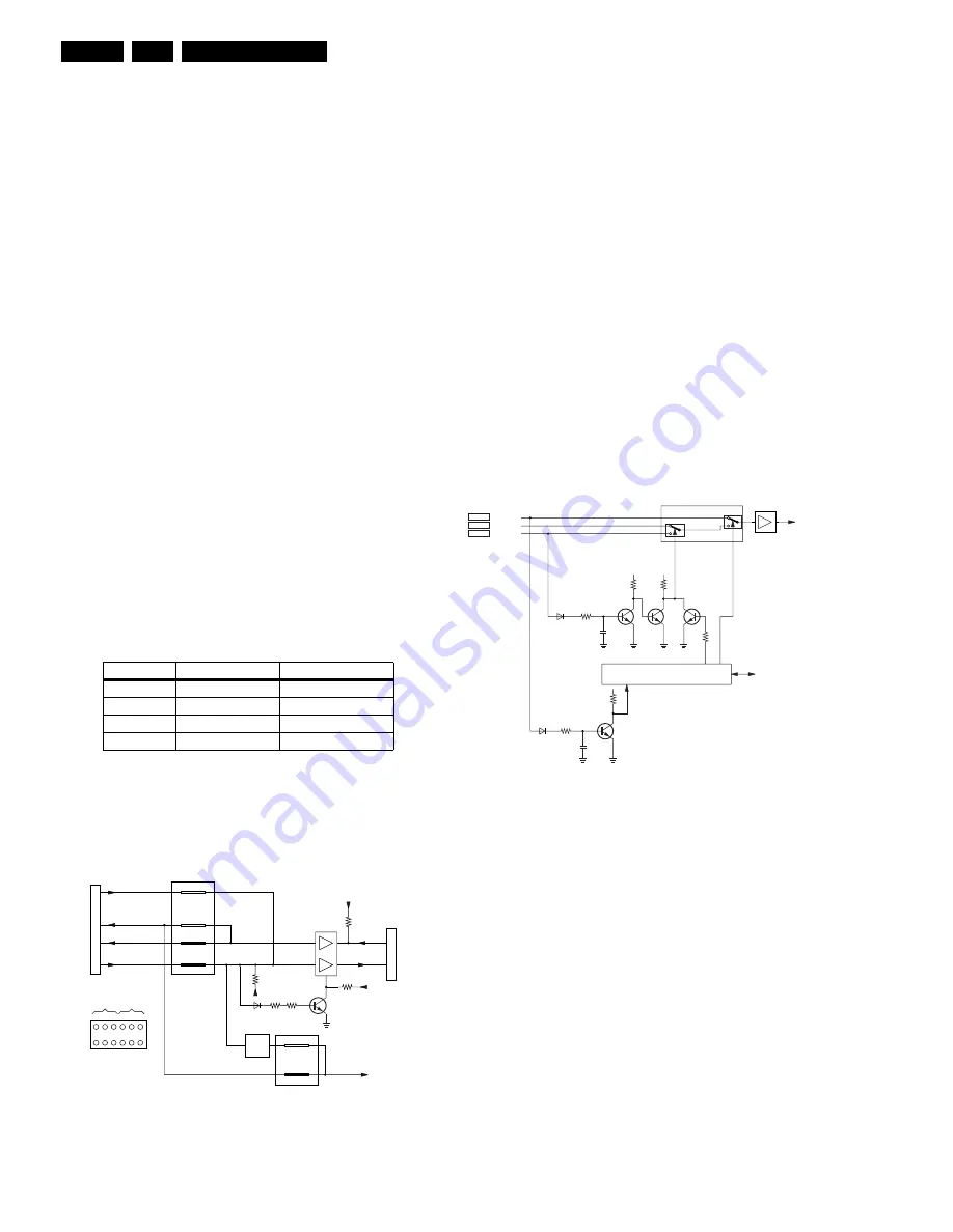
Figure 9-9 Block Diagram UART Circuitry
As the FM2x has no CONFIG_IDENT signal to "wake up" the
Receiver box, a "dummy" CONFIG_IDENT is derived from the
RXDO signal with the aid of a "one-shot generator" (item 7545).
In order to prevent the RXD-line from connecting to ground, a
protection circuit is added. This circuit puts the RXD-buffer into
tri-state if the input is connected to ground for more than 100
ms.
Because the diversity is realized with jumpers (connector
1519), there are no differences in panel stuffing for both
versions.
Teletext/On Screen Display (TXT/OSD)
The TXT/OSD-decoder in the OTC gets its video signal directly
on pin 5. The RGB-outputs are available on pins 77/78/79. Fast
blanking is realized by pin 80. The RAM (IC7001) of the
microprocessor is also used for the decoder.
Remote Control
The remote control uses RC6, because commands like "cursor
control in eight directions" are used.
For this chassis, there are three possible RC input sources:
•
RC_MON (coming from monitor),
•
RC_BOX (coming from box), and
•
RC_EXT (coming from an external source; this is not
used).
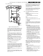
The selection is performed as shown in the figure below:
Figure 9-10 Block Diagram RC Selection Circuitry
When CONFIG_IDENT (for FTV1.9) or AYT (for FM2x) is
detected, the RC_MON is selected.
If there is no monitor connected, the RC_FRONT_SELECT
signal is always "low", so RC _MON cannot be selected (via
TS7749 and TS7751). After start up, when the I/O-expander is
not yet set via I2C, the RC_FRONT signal is connected to
RC_OUT.
Conn. 0303 F21R with FTV1.9 F21R with FM2x
Pin 4
Not used
RXDO
Pin 11
CONFIG_IDENT
TXDO
Pin 12
TXDO
Not used
Pin 15
RXDO
Not used
CL16532098_008.eps
180901
CONFIG_IDENT
TXDO
+5VSTB
1519
+5VSTB
3595
RXDO
7460
0303
3596
7545
1519
1
3
5
7
9
FTV2.3
FTV1.9
11
2
4
6
8 10 12
FTV2.3
FTV1.9
6
5
FTV1.9
4
3
FTV1.9
2
1
8
7
FTV2.3
+5VSTB
3577
0355
3576
3570
6571
7571
12
11
4
12
15
11
FTV2.3
10
9
one
shot
TO/FROM
MONITOR
TO µP
(SSP)
CL16532098_007.eps
180901
7881
7880
7740
I2C
RC_EXT_PRESENT_N
RC_FR
ONT_SEL
RC_FR
ONT_SEL_N
1
2
5
3
0
15
RC_OUT
to SSP
RC_FR
ONT_MON_SEL
I/O expander
RC_EXT_PRESENT
7749
RC_EXT
RC_FRONT
RC_MON
0313-C
0308-6
0303-9
7884
7751
1
0
Summary of Contents for F21RE
Page 7: ...Directions for Use EN 7 F21RE AB 3 3 Directions for Use ...
Page 8: ...Directions for Use EN 8 F21RE AB 3 ...
Page 9: ...Directions for Use EN 9 F21RE AB 3 ...
Page 10: ...Directions for Use EN 10 F21RE AB 3 ...
Page 11: ...Directions for Use EN 11 F21RE AB 3 ...
Page 12: ...Directions for Use EN 12 F21RE AB 3 ...
Page 13: ...Directions for Use EN 13 F21RE AB 3 ...
Page 14: ...Directions for Use EN 14 F21RE AB 3 ...
Page 15: ...Directions for Use EN 15 F21RE AB 3 ...
Page 16: ...Directions for Use EN 16 F21RE AB 3 ...
Page 17: ...Directions for Use EN 17 F21RE AB 3 ...
Page 18: ...Directions for Use EN 18 F21RE AB 3 ...
Page 19: ...Directions for Use EN 19 F21RE AB 3 ...
Page 20: ...Directions for Use EN 20 F21RE AB 3 ...
Page 21: ...Directions for Use EN 21 F21RE AB 3 ...
Page 22: ...Directions for Use EN 22 F21RE AB 3 ...
Page 23: ...Directions for Use EN 23 F21RE AB 3 ...
Page 24: ...Directions for Use EN 24 F21RE AB 3 ...
Page 25: ......
Page 114: ...Revision List EN 114 F21RE AB 11 11 Revision List First release ...

