Circuit Descriptions, List of Abbreviations, and IC Data Sheets
EN 97
F21RE AB
9.
U/V (colour difference signals) is also sampled with nine bits.
These two nine bit data streams are multiplexed to four bit data
streams. As the perception of colours by the human eye is less
sensitive to luminance, this reduction is allowed.
Interlaced to progressive scan conversion
The main function of the PICNIC is the "Analogue to Digital"
conversion, spatial noise reduction, histogram functions (like
Dynamic Contrast and Black Stretch) for YUV, and HV-sync
processing. Also, the line frequency is doubled.
De-interlacing itself is realized in the FALCONIC (Field And
Line CONverter IC).
Further features of the PICNIC:
•
Dual Screen Compression. The PICNIC can provide
horizontal video compression up to 50 %. The compress
mode can be used to display dual screens.
•
The Panorama Mode. To fit 4:3 pictures into a 16:9
display, it is possible to apply a panoramic horizontal
distortion, to make a screen-fitting picture without black
sidebars or lost video. The centre horizontal gain is
programmable and the side gain is automatically adapted
to make a screen-fit.
•
Automatic Aspect Ratio Adaptation (AARA). This
feature uses data from the "black bar detection circuit" to
adapt the vertical and horizontal amplitude to an aspect
ratio belonging to the display, without the black bars.
•
Dynamic Contrast. To make the contrast (black/white)
range wider, Philips has invented Dynamic Contrast. It
uses the digital memory used in 100 Hz sets. It measures
every A-field (25 x per second), and digitally analyses
where on the greyscale most of the image is located. If it is
a relatively dark image, the lighter part of that image is
stretched towards white, so that more contrast will become
visible in that picture. If it is a relatively light image, the
darker part of that image is stretched towards black, so that
these darker parts will have more contrast. When the
image is in the middle of the greyscale, both dark and light
parts are stretched.
FALCONIC (Diagram L3)
Besides "Natural Motion", The FALCONIC (Field And Line
CONverter IC) has the following functions:
•
Line flicker reduction (Digital Scan).
•
Noise reduction (DNR, Dynamic Noise Reduction).
•
Vertical Zoom.
•
Movie phase detection.
•
Progressive scan.
•
Variable vertical sample rate conversion.
•
Synchronous No parity Eight bit Reception and
Transmission interface (SNERT).
422 processing
The FALCONIC can do "422" processing. This means eight
data lines for Y and eight data lines for U/V (844 = 422).
Therefore, the bandwidth for the colour difference increases:
the bandwidth for Y remains 6 MHz, and the bandwidth for
colour difference is now 3 MHz. This means that the picture for
DVD is much better. For this extra bandwidth, an extra field
memory is used: IC7640.
Improved motion detection (Natural Motion)
This set utilizes AB'A'B scanning, a new sample for Natural
Motion.
The FALCONIC has an extra advantage for motion detection:
the maximum number of pixels that can be followed in AB’A’B
scanning is higher: This produces a more natural motion, even
with very fast movements.
Improved line flicker reduction (Digital Scan)
The FALCONIC offers motion compensated line flicker
reduction. This virtually leads to complete elimination of line
flicker.
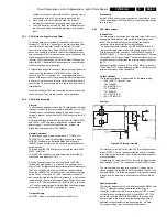
Figure 9-13 Block Diagram Digital Scan
Bus A is the input bus for the FALCONIC. The data comes from
the two memory ICs (IC7602 and 7634) and the FALCONIC will
cluster this data. It is possible to connect two field memories to
the FALCONIC. The output of the FALCONIC is fed back to the
PICNIC via bus D.
The FALCONIC has two possible configurations:
•
Economy mode: In this mode, only Field Memory 2 is
mounted (saving the cost of Field Memory 3). In this
configuration, the full frame store can be made by a factor
2 data compression, using 2 dimensional DPCM
techniques. This results in a performance with more
quantisation noise, while maintaining improved MEMC
quality. In this case, a full "422" processing cannot be
achieved. Only the 422-DPCM is possible.
•
Full functionality mode: This configuration uses Field
Memory 2 and 3. Therefore, no picture performance
concessions are made here. In this mode, all FALCONIC
features can be applied optimally. However, to be able to
perform full "422" processing, the FM1 must be extended
with an extra 4 bits, for a total of 16 bits.
Power Supply and RESET Circuit
Besides the two incoming voltages, 8V6 and 5V2, two
stabilizers (for power consumption reasons) are used for the
3V3 (3V3A and 3V3B).
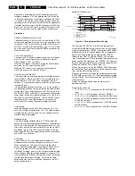
Figure 9-14 Block Diagram Reset Circuitry
Via the reset circuit (TS7600/TS7601) a pulse of 20 ms is
generated for the
µ
P (in the PICNIC) and for the ROM. After
power "on", the 3V3 is built up, which is derived from the 5V2.
As long as the 5V2 is below the 3V3, the 3V3 follows the 5V2.
10
13
Y
C1 C8
UV
C5 C8
BUS F
BUS A
WE_D
BUS D
BUS E
BUS B
BUS C
CL 16532023_049.eps
210901
MEM1A
MEM1B
MEM3
MEM2
FALCONIC
IC7638
IC7640
Y01
D8
UVD1
D8
RE
MFO1 MF016
YD0 YD7
UV D0 UV0
YB0 YB7
UVB0 UVB3
FE04 FF11
FE00 FE03
YC0 YC7
UVC0 UVC3
UV
C1 C4
WE_B
IEE
CL 32
CL 32
BUS D
BUS C
PICNIC
CL 32
CL 32
CL 16
CL 16
7634
7602
RE
RE
OE
OE
3V3
3V3
SR
CK
SW
CK
SR
CK
SW
CK
RSTR
RSTR
WE
IE
OE
WE IE
OE
+5V
+5V
+5V
+5V
CL 32
CL 32
R
S
T
R
R
S
T
W
W
E
I
C
I
E
I
C
(100Hz)(50Hz)
7601
7600
+5V
3683
3605
3603
3610
3609
3601
3604
3680
20mS
2mS
3608
C2690
C2656
7613
7612
+5V
+3,3VB
DETECTION 3V3
CL 16532023_050.eps
240901
PICNIC
6 µP RESET
7 WD RESET (WATCH DOG)
5606
5640
7631
7630
5V
8V6
5V
3V3B
+3V3F
3V3P
3V3A
8V6
Summary of Contents for F21RE
Page 7: ...Directions for Use EN 7 F21RE AB 3 3 Directions for Use ...
Page 8: ...Directions for Use EN 8 F21RE AB 3 ...
Page 9: ...Directions for Use EN 9 F21RE AB 3 ...
Page 10: ...Directions for Use EN 10 F21RE AB 3 ...
Page 11: ...Directions for Use EN 11 F21RE AB 3 ...
Page 12: ...Directions for Use EN 12 F21RE AB 3 ...
Page 13: ...Directions for Use EN 13 F21RE AB 3 ...
Page 14: ...Directions for Use EN 14 F21RE AB 3 ...
Page 15: ...Directions for Use EN 15 F21RE AB 3 ...
Page 16: ...Directions for Use EN 16 F21RE AB 3 ...
Page 17: ...Directions for Use EN 17 F21RE AB 3 ...
Page 18: ...Directions for Use EN 18 F21RE AB 3 ...
Page 19: ...Directions for Use EN 19 F21RE AB 3 ...
Page 20: ...Directions for Use EN 20 F21RE AB 3 ...
Page 21: ...Directions for Use EN 21 F21RE AB 3 ...
Page 22: ...Directions for Use EN 22 F21RE AB 3 ...
Page 23: ...Directions for Use EN 23 F21RE AB 3 ...
Page 24: ...Directions for Use EN 24 F21RE AB 3 ...
Page 25: ......
Page 114: ...Revision List EN 114 F21RE AB 11 11 Revision List First release ...


