
FC9184/01 / FC9184/11
2-9
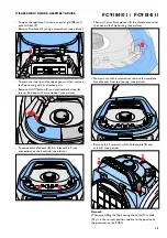
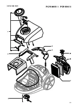
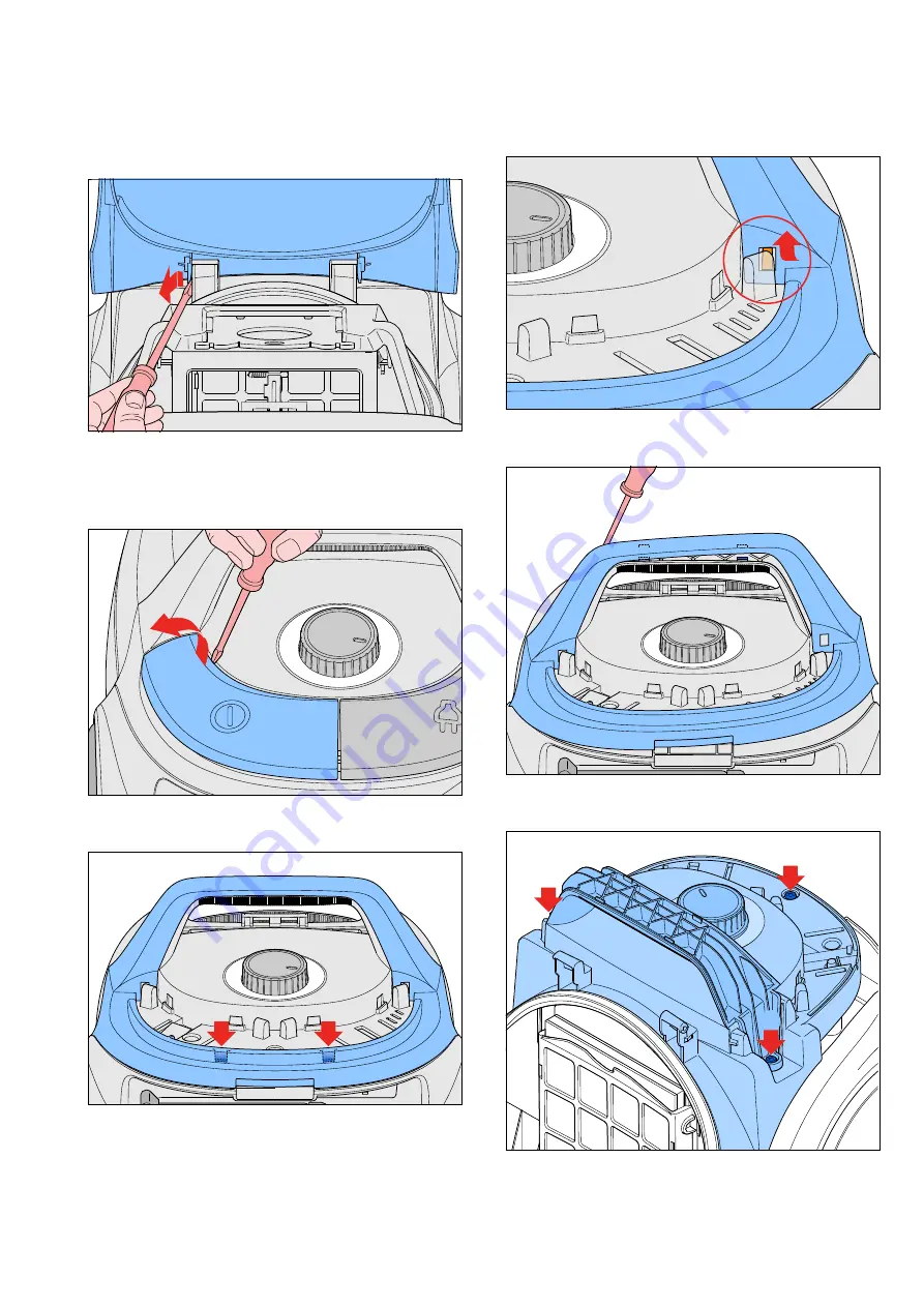
• To open the appliance, first remove outlet grill (
28
) and
exhaust filter (
7
).
• Remove Dustcover (
1
) using a screwdriver (see picture).
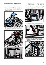
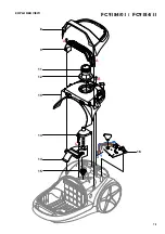
• To reach the inner parts for repair you must first remove
the Top housing with its attached parts.
• Remove On/Off button (
5
) and cordwinder button (
6
),
this can be done with a screwdriver (see picture).
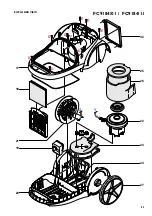
• To remove Handle cover (
8
) first release the 2 snap
connections on the backside (see picture).
• Then with a small screwdriver lift the Handle cover over
the nock on the Top housing (see picture).
• Now you can with a screwdriver remove the complete
Handle cover from the housing (see picture).
• Remove the 2 screws
A
which hold Handle (
9
) and
screw
B
(see picture).
A
A
B
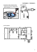
Remark
:
When assembling the Top housing check that Turn knob
(
11
) is in the correct position relative to the position of
the potmeter on the PCBA.
DISASSEMBLY- AND RE-ASSEMBLY ADVISE


