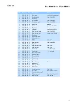
FC9184/01 / FC9184/11
4-9
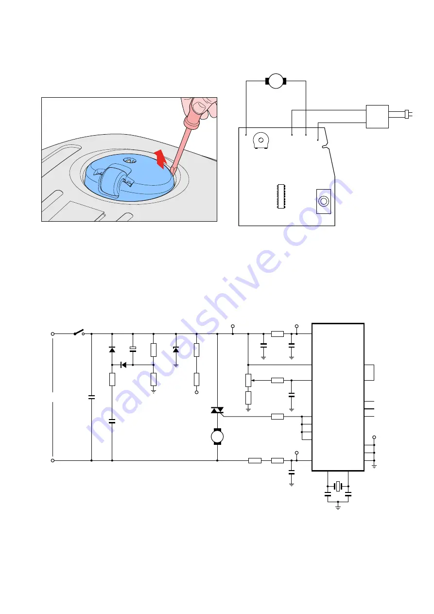
M
Motor
S1
Mains
C2
D3
D2
C1
R7
R10
R8
R9
R6
W5
W2
W1
D1
Blue
Brown
R3
R2
Q1
Triac
C3
5
6
17
7
9
10
15
16
11
8
1
12
2
3
4
18
C7
C6
C4
R5
R4
C5
R11
P1
B1
U1
HT46C47
13
14
TP2
TP1
TP5
TP3
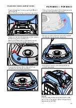
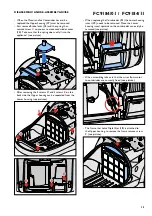
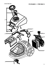
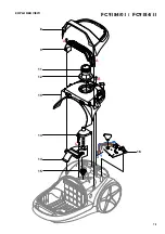
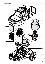
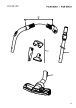
DISASSEMBLY- AND RE-ASSEMBLY ADVISE
• To replace Caster assy (
4
) turn the appliance upside
down, push the Caster assy with a screwdriver up and
pull it out (see picture).
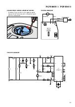
WIRING DIAGRAM
MOTOR
POWER
MODULE
Brown
Blue
CORD WINDER
Black/White
Black
M
CIRCUIT DIAGRAM