Service Modes, Error Codes, and Fault Finding
EN 27
FHP PDP
5.
Remark:
Do not interchange boards between different PDPs,
this can damage your PDP
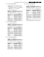
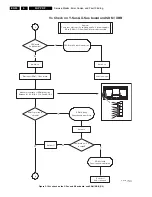
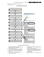
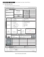
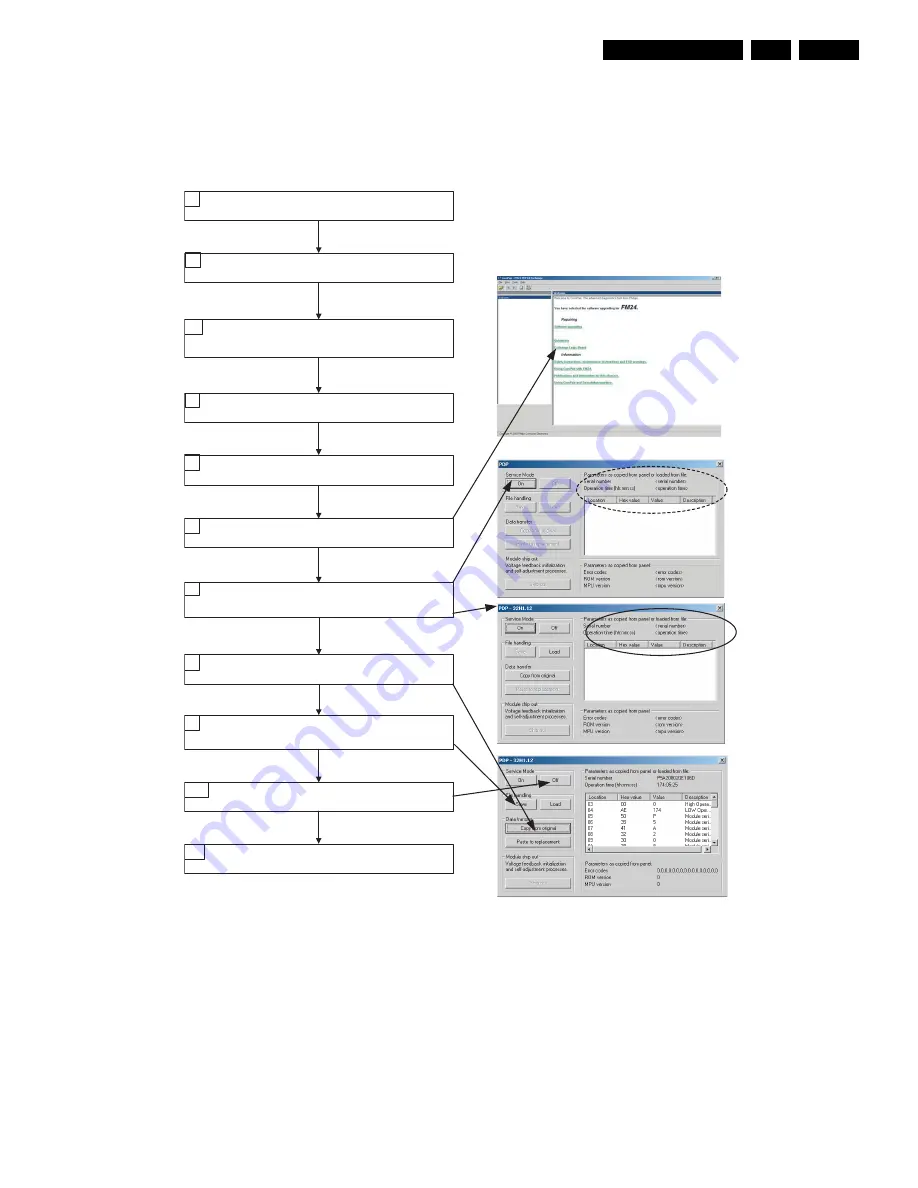
Figure 5-17 Logic Board Exchange (1/2)
1.
Unscrew the SCAVIO panel. Now you can reach the cable
going to connector CN1 on the Logic Board
2.
Disconnect the cable from the SCAVIO panel at connector
0301. Leave the rest connected!
3.
Connect the ComPair I2C cable as given in this diagram.
4.
Switch on the set. It will go to stand-by or protection mode.
5.
Click the link in ComPair to open the Logic Board exchange
window.
6.
Click the 'On' button. In the title bar the module type will
appear: 37H1.11, 42H2, or something similar.
7.
Click button 'Copy from original'
8.
The data is read from the EEPROM on the logic board and
displayed in the list.
9.
Use the 'Save' button to save the information to a file. This
is optional, but better safe than sorry!
Note:
If you close the window without saving, all settings
will be lost. If you intend to close this window before
replacing the board, you should save the settings so you
can load them later.
10. Click the 'Off' button.
11. Switch off the set and replace the Logic Board with another
one.
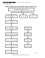
Logic Board Exchange (1)
1. Copy NVM Data from defective Logic Board
Unscrew the SCAVIO Panel
1.
Disconnect the LVDS Cable from the SCAVIO at
(CN0301)
2.
Switch on the set
4.
Set will go into protection or in standby
5.
Click the link in ComPair to open the Logic Board
exchange window
6.
Click the "On" button.
In the titlel bar the module type will appear
7.
Click button "copy from original"
8.
Use the "Save" button to save the information to a file
9.
Click the "Off" button
10.
Switch off the set and replace the Logic board
11.
Connect the service Cable (12nc 9965 000 23434) to
the LVDS connector on the FME Logic board
3.
E_14580_021.eps
111005

