Service modes, fault finding and repair tips
GB 25
FTV1.9EE
5.
Id: F19DE11.0_12345 (1)
Operation Hours: LLLLL (2)
Errors: 14 08 02
--------------------------------------------------
Software identification of the main micro controller (F19DBC
X.Y_#####)
•
F19D is the chassis name for FTV1.9 Display
•
B is the region identification
•
C is the language cluster
•
X = main version number
•
Y = subversion number
•
##### are the last 5 digits of the 12nc number
(2) Operation hours: Normal display operation in hours
(resolution 1 hrs)
(3) Errors: The contents of the error buffer (max. 10 errors).
The last error that occurred is displayed at the most left
position. When the errorlist is empty "No errors" is displayed.
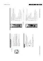
Access to normal user menu:
Pressing the "MENU" button on the remote control will enter the
normal user menu (TV lock, Installation, Brightness, colour and
contrast) while "SAM" remains displayed in top of screen.
Pressing the "MENU" key again will return to the last SAM
status.
OSD:
Pressing the "OSD" button on the remote control shows all
OSD information (incl. error buffer).
Access to SDM:
Pressing the "DEFAULT" button on the DST
SAM menu control:
Menu items can be selected with the "UP" or "DOWN" key.
Entry into the selected items (sub menus) is done by the
"LEFT" or "RIGHT" key. The selected item will be highlighted.
With the same "LEFT/RIGHT" keys, it is possible to increase/
decrease the value of the selected item.
Return to the former screen by pushing the "MENU" button.
The item values are stored in NVM if the sub menu is left.
5.3.3
Customer Service Mode
FTV1.9 sets are equipped with the "Customer Service Mode"
(CSM). CSM is a special service mode that can be activated
and de-activated by the customer, upon request of the service
technician/dealer during a telephone conversation in order to
identify the status of the set. This CSM is a 'read only' mode,
therefore modifications in this mode are not possible.
Entering the Customer Service Mode:
•
By pressing simultaneously the "LOCAL MENU" button on
the local keyboard and the button (Mute) on the RC.
Exit of the Customer Service Mode:
•
pressing any key on the remote control handset (except
"P+" or "P-")
•
switching off the TV set with the mains switch.
The screen has the following set-up:
--------------------------------------------------
CUSTOMER SERVICE MENU 1
1.
SW Ver.
2.
Code 1
3.
Code 2
4.
PP Volume
5.
PP Colour
6.
PP Brightness
7.
PP Contrast
8.
PP Headphone volume
9.
Sharpness
10. Child lock
11. External Center Sound
--------------------------------------------------
Pressing the "P+" button on the RC shows page 2 of the CSM.
Pressing "P-" shows again page 1 of the CSM.
--------------------------------------------------
CUSTOMER SERVICE MENU 2
1.
Incredible Sound
2.
DNR
3.
Noise Figure
4.
Colour System
5.
TV System
6.
Audio System
7.
Tuned bit
8.
DVD/Photo CD
9.
Sleep Timer
10. On Timer
--------------------------------------------------
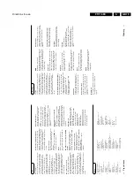
Display in the [MenuItems] field:
1.
Software Identification: AAA=Chassis name, BB=Function
name, C=Language cluster, X=main version nr. Y=sub
version nr.
2.
The last 5 error nr's in the error buffer(This line will be
empty when there are no errors)
3.
The first 5 error nr's in the error buffer.(This line will be
empty when there are no errors)
4.
Personal preference value of the volume
5.
Personal preference value of the colour
6.
Personal preference value of the brightness
7.
Personal preference value of the contrast
8.
Personal preference value of the headphone volume
9.
Sharpness level
10. Child Lock status On/Off indication
11. Dolby Center Sound status On/Off indication
12. Incredible Sound status On/Off indication
13. DNR status
14. Indication of the signal quality
15. Colour System of selected program: PAL, SECAM or
NTSC
16. Video system of selected program: BG, DK, I, L, M38.9 or
MN
17. Audio system of selected program: Sound Muted, Mono,
Stereo, Dual I, Dual II, Digital Mono, Digital Stereo, Digital
Dual I, Digital Dual II
18. Indication of whether the selected program is Tuned or not
19. Indication for whether or not DVD/Photo CD id selected
20. Only if the [value] of [SleepTimer] is NOT "0"
21. Only if the [starttime] of [OnTimer] is defined
5.4
Error code buffer and error-codes
The error code buffer contains all errors detected since the last
time the buffer was erased. The buffer is written from left to
right.
In case of non-intermittent faults, clear the error buffer before
starting the repair to prevent that "old" error codes are present.
If possible, check the entire content of the error buffers. In
some situations an error code is only the RESULT of another
error code (and not the actual cause).
Note: a fault in the protection detection circuitry can also lead
to a protection
The error code buffer will be cleared in the following cases:
•
exiting SDM or SAM with the "Standby" command on the
remote control
•
transmitting the commands "DIAGNOSE-9-9-OK" with the
DST.
The error buffer is not reset by leaving SDM or SAM with the
mains switch.
Examples:
ERROR: 0 0 0 0 0 : No errors detected
ERROR: 6 0 0 0 0 : Error code 6 is the last and only detected
error
ERROR: 5 6 0 0 0 : Error code 6 was first detected and error
code 5 is the last detected (newest) error
Summary of Contents for FTV1.9EE
Page 45: ...Electrical diagrams and print layouts 45 FTV1 9EE 7 Teletext component side ...
Page 46: ...Electrical diagrams and print layouts 46 FTV1 9EE 7 Teletext copper side ...
Page 49: ...Electrical diagrams and print layouts 49 FTV1 9EE 7 Euro I O panel ...
Page 50: ...Electrical diagrams and print layouts 50 FTV1 9EE 7 Euro I O panel ...
Page 51: ...Electrical diagrams and print layouts 51 FTV1 9EE 7 Euro I O component side ...
Page 52: ...Electrical diagrams and print layouts 52 FTV1 9EE 7 Euro I O copper side ...
Page 54: ...Electrical diagrams and print layouts 54 FTV1 9EE 7 Feature box component side ...
Page 55: ...Electrical diagrams and print layouts 55 FTV1 9EE 7 Feature box copper side ...
Page 56: ...Electrical diagrams and print layouts 56 FTV1 9EE 7 Incredible sound Incredible sound ...
Page 57: ...Electrical diagrams and print layouts 57 FTV1 9EE 7 ECO NICAM ...
Page 74: ...Electrical diagrams and print layouts 74 FTV1 9EE 7 Personal notes Personal notes ...


