Service modes, fault finding and repair tips
GB 27
FTV1.9EE
5.
•
ComPair helps you to quickly get an understanding how to
repair the FTV1.9 in short time by guiding you step by step
through the repair procedures.
•
ComPair allows very detailed diagnostics (on I2C level)
and is therefore capable of accurately indicating problem
areas. You do not have to know anything about I2C
commands yourself; ComPair takes care of this.
•
ComPair speeds up the repair time since it can
automatically communicate with the FTV1.9 (when the
micro processor is working) and all repair information is
directly available. When ComPair is installed together with
the SearchMan FTV1.9 electronic manual, schematics and
PCBs are only a mouse-click away.
ComPair consists of a Windows based fault finding program
and an interface box between PC and the (defective) product.
The ComPair interface box is connected to the PC via a serial
or RS232 cable. In case of the FTV1.9 chassis, the ComPair
interface box and the FTV1.9 communicate via an I2C cable
(bi-directional) and via infra red communication (uni-
directional; from ComPair interface box to FTV1.9
The ComPair fault finding program is able to determine the
problem of the defective television. ComPair can gather
diagnostic information in 2 ways:
1.
Communication to the television (automatic)
2.
Asking questions to you (manually)
ComPair combines this information with the repair information
in its database to find out how to repair the FTV1.9.
Automatic information gathering
Reading out the error buffer, ComPair can automatically read
out the contents of the entire error buffer.
Diagnosis on I2C level. ComPair can access the I2C bus of the
television. ComPair can send and receive I2C commands to
the micro controller of the television. In this way it is possible for
ComPair to communicate (read and write) to devices on the
I2C busses of the FTV1.9.
Manual information gathering
Automatic diagnosis is only possible if the micro controller of
the television is working correctly and only to a certain extend.
When this is not the case, ComPair will guide you through the
fault finding tree by asking you questions and showing you
examples. You can answer by clicking on a link (e.g. text or
waveform pictures) that will bring you to the next step in the
faultfinding process.
A question could be: Do you see snow? (Click on the correct
answer)
YES / NO
An example can be: Measure testpoint I7 and click on the
correct oscillogram you see on the oscilloscope
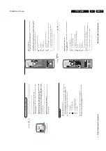
Figure 5-1
By a combination of automatic diagnostics and an interactive
question/answer procedure, ComPair will enable you to find
most problems in a fast and effective way.
Additional features
Beside fault finding, ComPair provides some additional
features like:
•
Uploading/downloading of pre-sets
•
Managing of pre-set lists
•
Emulation of the Dealer Service Tool
5.6.2
Searchman (Electronic Service Manual)
If both ComPair and SearchMan are installed, all the
schematics and PCB's of the faulty set are available when
clicking on the hyper-link of a schematic or a PCB in ComPair.
Example : Measure the DC-voltage on capacitor C2568
(Schematic/Panel) at the Monocarrier.
Clicking on the PCB hyper-link, automatically shows the PCB
with a high-lighted capacitor C2568. clicking on the schematic
hyper-link, automatically shows the position of a high-lighted
capacitor C2568 at the schematic.
5.6.3
Connecting the ComPair interface
The ComPair Browser software should be installed and setup
before connecting ComPair to the FTV1.9. (See the ComPair
Browser Quick Reference Card for installation instructions.)
1.
Connect the RS232 interface cable to a free serial (COMM)
port on the PC and the ComPair interface PC connector
(connector marked with "PC").
2.
Place the ComPair interface box straight in front of the
television with the infrared window (marked "IR") directed
to the television LED. The distance between ComPair
interface and television should be between 0.3 and 0.6
meter. (Note: make sure that (also) in the service position,
the ComPair interface infra red window is pointed to the
standby LED of the television set (no objects should block
the infra red beam)
3.
Connect the mains adapter to the connector marked
"POWER 9V DC" on the ComPair interface
4.
Switch the ComPair interface OFF
5.
Switch the television set OFF with the mains switch
6.
Remove the rear cover of the television set
7.
Connect the interface cable (4822 727 21641) to the
connector on the rear side of the ComPair interface that is
marked "I2C" (See Figure 5.3)
8.
Connect the other end of the interface cable to the
ComPair connector on the monocarrier.
9.
Plug the mains adapter in the mains outlet and switch ON
the interface. The green and red LED's light up together.
The red LED extinguishes after approx. 1 second (the
green LED remains lit).
10. Start-up Compair and select "File" menu, "Open...:; select
"FTV1.9 Fault finding" and click "OK"
11. Click on the icon (Fig. 5-2) to switch ON the communication
mode (the red LED on the Compair interface wil light up)
12. Switch on the television set with the mains switch
13. When the set is in standby. Click on "Start-up in ComPair
mode from standby" in the ComPair FTV1.9 fault finding
tree, otherwise continue.
Figure 5-2
Figure 5-3
I7 B7502
1V / div DC
10
µ
s / div
86532027_003.EPS
050898
PC
VCR
I
2
C
Power
9V DC
Summary of Contents for FTV1.9EE
Page 45: ...Electrical diagrams and print layouts 45 FTV1 9EE 7 Teletext component side ...
Page 46: ...Electrical diagrams and print layouts 46 FTV1 9EE 7 Teletext copper side ...
Page 49: ...Electrical diagrams and print layouts 49 FTV1 9EE 7 Euro I O panel ...
Page 50: ...Electrical diagrams and print layouts 50 FTV1 9EE 7 Euro I O panel ...
Page 51: ...Electrical diagrams and print layouts 51 FTV1 9EE 7 Euro I O component side ...
Page 52: ...Electrical diagrams and print layouts 52 FTV1 9EE 7 Euro I O copper side ...
Page 54: ...Electrical diagrams and print layouts 54 FTV1 9EE 7 Feature box component side ...
Page 55: ...Electrical diagrams and print layouts 55 FTV1 9EE 7 Feature box copper side ...
Page 56: ...Electrical diagrams and print layouts 56 FTV1 9EE 7 Incredible sound Incredible sound ...
Page 57: ...Electrical diagrams and print layouts 57 FTV1 9EE 7 ECO NICAM ...
Page 74: ...Electrical diagrams and print layouts 74 FTV1 9EE 7 Personal notes Personal notes ...


