background image

Service Information

Service

Service

Service

Product Service Group CE Audio

3139 785 30073

2000 - 06 - 03

FW-C399

A02 - 159

CORRECTION TO SERVICE MANUAL

Front Page content:

The correct 3-CDC Module should be  3CDC-LLC-MCD1
instead of 3CDC-LLC-MB

CHANGES DURING PRODUCTION

MMPWR 100W Module

* From wk152 onwards a new Spring, Trans is introduced to

clamp IC7257 (L7805CP) onto heatsink instead of direct
screw mounting.  This spring, Trans is availble under service
code:  4822 492 11735

* From wk218 onwards a new pt 5 Left/Right & Power Supply

board is introduced due to additon of diode 6999 into same
location as 9495.  This change is for other set application &
can be recognized by printing mark ....113_34345_01/...

* From wk218 onwards new Mains & Mains socket pc boards

is introduced due to process improvement.  The board can
be recognized by printing mark ....3139_113_34822_01.

New pc board layout drawing is enclosed.

Already published Service Informations:

Summary of Contents for FW-C399/25

Page 1: ...399 25 refers to FW C399 22 except the following adaptations 385 2422 070 98147 Mains Cord FW C399 30 refers to FW C399 22 except without RDS NEWS and the following adaptations 1 Mechanical Accessories 101 3139 118 17081 Cabinet Front 128 3139 118 16750 Window Display 142 Deleted 256 3139 114 73140 Panel Rear 385 2422 070 98148 Mains Cord 387 3139 115 21120 Instruction For Use 2 Front Board Delete...

Page 2: ...re below Enclosed is the complete new chapter 10 for the new module Already published Service Informations A02 159 3139 785 30073 MMPWR 100W MODULE From wk238 onwards begin with 37 versions the following changes are make to improve reliability of the Power ampli fier Delete 2360 2363 3371 and 3374 Add 2361 5322 121 42386 100nF 10 50V 2364 5322 121 42386 100nF 10 50V 3372 4822 053 10478 4R7 5 1W 33...

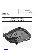
Page 3: ...nts 10 2 Blockdiagram 10 5 Component Layout Main Board 10 6 Circuit Diagram part1 10 7 Component Layout Main Board 10 8 Circuit Diagram part2 10 9 Exploded View 10 10 Partslist 10 12 3CDC LLC DA11 3 Disc Carousel Changer Layout stage 3 ...

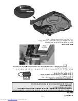
Page 4: ... WHEN CONNECTING A NEW CD MECHANISM THAT S WHY BESIDES THE SAFETY MEASURES LIKE SWITCH OFF POWER SUPPLY ESD PROTECTION ADDITIONAL ACTIONS MUST BE TAKEN BY THE REPAIR TECHNICIAN fig 1 Attention The laser diode of this CD drive is protected against ESD by a solder joint which shortcircuits the laserdiode to ground For proper functionality of the CD drive this solder joint must be removed after conne...

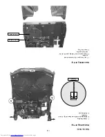
Page 5: ... of Tray Service hints 1 Open the tray 2 Release 2x catch as shown in fig 2 and Detail A 3 Pull tray out fig 2 Assembling of Tray 1 Turn Cam pos 48 clockwise to end position 2 If necessary move Guiding pos 49 to the right end position 3 Insert the Tray ...

Page 6: ...10 4 Service Position ...
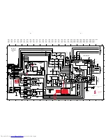
Page 7: ...COGNITION 6 7 4 5 1882 closed if carousel is in Position 1 1883 1883 open if carousel is in a valid Play Position CD RW 3V CD DA 0V EQ Selection Closed if the tray is in one endposition Open during movement Open if the drive is in one endposition Closed during movement VDD pin 16 EN1 pin 15 Power on FOCUS MOTOR RADIAL MOTOR SLEDGE MOTOR MOTOR TURNTABLE 55 54 56 59 1 16 13 9 12 9 12 13 16 6 7 2 780...

Page 8: ...8 E4 3799 E4 3800 E3 3801 E4 3802 F4 3803 D4 3804 C3 3805 D4 3806 D4 3807 D4 3808 D4 3809 D2 3811 F4 3813 F4 3814 D4 3818 F3 3819 C3 3820 F3 3821 F3 3822 F3 3825 E3 3826 E3 3827 D4 3828 D2 3831 C2 3832 C3 3833 F4 3834 F4 3837 D2 3838 D2 3839 E2 3840 E3 3841 D2 3842 D2 3843 E2 3844 F2 3845 D2 3846 E2 3847 G2 3849 E2 3850 E1 3853 E4 3858 B5 3859 B5 3860 B4 3861 C4 3862 C4 3863 D2 3864 C4 3865 B4 386...

Page 9: ... F C 3863 G13 MP858 G8 MP859 E10 MP860 C2 MP872 C15 MP873 H4 MP875 F13 MP876 E2 MP877 E3 MP878 B13 MP879 B11 39K 3721 47n 2835 470n 2894 100n 2820 2812 33p 2834 33p GND GND 3704 1R 27p 2856 3800 2826 47u 3802 2K2 3795 10K 3803 33p 2833 2836 47n 1810 TF01 EBUGND 2807 2815 GND GND 3 3V 330K 3849 1K 3837 58 VSSD3 35 WCLI 28 WCLK 470R 3873 63 V1 34 V2 V3 61 V4 62 V5 5 VDDA1 17 VDDA2 52 VDDD1P 57 VDDD2...

Page 10: ...8 E4 3799 E4 3800 E3 3801 E4 3802 F4 3803 D4 3804 C3 3805 D4 3806 D4 3807 D4 3808 D4 3809 D2 3811 F4 3813 F4 3814 D4 3818 F3 3819 C3 3820 F3 3821 F3 3822 F3 3825 E3 3826 E3 3827 D4 3828 D2 3831 C2 3832 C3 3833 F4 3834 F4 3837 D2 3838 D2 3839 E2 3840 E3 3841 D2 3842 D2 3843 E2 3844 F2 3845 D2 3846 E2 3847 G2 3849 E2 3850 E1 3853 E4 3858 B5 3859 B5 3860 B4 3861 C4 3862 C4 3863 D2 3864 C4 3865 B4 386...

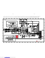
Page 11: ...ec RIGHT EBUGND 2860 10u 2878 220p 3874 10K 3858 47K 1K 3891 BAS216 6876 1880 10K 3878 9 12 5 3 4 8 11 15 7871 TDA7073A 14 10 2 1 6 7 16 13 OUT1 220R 3898 1 2 3 4 5 GNDA 1875 FE ST VK N 220R 3887 47p 2877 3744 10K 3741 22K 7875 BC847B 3899 100R 3R3 3851 4811 3872 10K 2867 220p 3746 10K 3860 220p 2862 3715 100K 10K 22K 3713 3879 100K 2858 220u 470R 3893 10K 3714 3742 22K 220p 2893 BC847B 7812 8 4 T...

Page 12: ...SPRING GUIDING 44 3103 304 06890 GEAR 3 45 3103 304 06980 NAIL FIXATION 46 3103 304 06880 GEAR 2 47 3103 304 66530 BRACKET LOAD 48 3103 304 06910 CAM 49 3103 304 66510 GUIDING 51 3103 304 06900 GEAR 4 52 3103 304 06870 GEAR 1 53 3103 304 06960 PULLEY FRAME 54 3103 304 66910 DRIVING BELT DRAWER 55 4822 361 10753 TRAY MOTOR 56 4822 502 12548 SCREW M2 6X3 5 57 3103 304 69880 COVER DA11 59 4822 466 12...

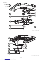
Page 13: ...10 11 3CDC LC Drawer assy 1999 09 13 37 20 32 35 33 36 29 31 34 24 30 3x 27 24 22 20 23 25 21 26 28 Drawer top view Drawer bottom view X spare part non spare part Y ...

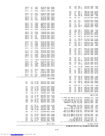
Page 14: ...855 4822 126 10326 180pF 5 50V 2856 4822 126 13691 27pF 1 63V 2857 5322 126 11583 10nF 10 63V 2858 4822 124 12245 220µF 20 16V 2860 4822 124 11947 10µF 20 16V CAPACITORS 2861 4822 124 11947 10µF 20 16V 2862 4822 126 13883 220pF 5 50V 2863 4822 126 13883 220pF 5 50V 2865 4822 126 14494 22nF 10 25V 2867 4822 126 13883 220pF 5 50V 2872 3198 024 44730 47nF 5 50V 2873 4822 124 40196 220µF 20 16V 2875 4...

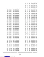
Page 15: ...632 100kΩ 1 0 06W 3882 4822 117 12925 47kΩ 1 0 06W 3883 4822 117 10833 10kΩ 1 0 1W 3884 4822 051 30271 270Ω 5 0 06W RESISTORS 3885 4822 117 10833 10kΩ 1 0 1W 3886 4822 117 12925 47kΩ 1 0 06W 3887 4822 051 30221 220Ω 5 0 06W 3888 4822 117 10833 10kΩ 1 0 1W 3889 4822 051 20471 470Ω 5 0 1W 3890 4822 051 30102 1kΩ 5 0 06W 3891 4822 051 30102 1kΩ 5 0 06W 3892 4822 051 20471 470Ω 5 0 1W 3893 4822 051 30...

Page 16: ...7808 4822 130 60511 BC847B 7809 4822 130 60511 BC847B 7810 4822 130 60511 BC847B 7812 4822 130 60511 BC847B 7874 4822 130 60511 BC847B 7875 4822 130 60511 BC847B INTEGRATED CIRCUITS 7803 5322 209 82941 LM358D Dual Opamp 7805 4822 209 33165 TDA1308T N1 Dual Opamp 7806 4822 209 32852 TDA7073A N2 Servo Driver 7807 4822 209 32852 TDA7073A N2 Motor Driver 7871 4822 209 32852 TDA7073A N2 Motor Driver 78...

Page 17: ...o heatsink instead of direct screw mounting This spring Trans is availble under service code 4822 492 11735 From wk218 onwards a new pt 5 Left Right Power Supply board is introduced due to additon of diode 6999 into same location as 9495 This change is for other set application can be recognized by printing mark 113_34345_01 From wk218 onwards new Mains Mains socket pc boards is introduced due to ...

Page 18: ...9 113 3482 pt2 dd wk0222 This assembly drawing shows a summary of all possible versions For components used in a specific version see schematic diagram and respective parts list 3139 113 3482 pt2 dd wk0222 MAINS BOARD COPPER SIDE VIEW ...

Reviews: