To VU Meter Housing (Right) Board
To Front Display Board
A
B
C
D
1830 C1
1831 D4
2830 D2
2831 D3
2832 C2
2833 A2
2834 D3
1
2
3
4
1
2
3
4
A
B
C
D
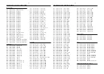
3831 C2
3832 D2
3833 D3
3834 D3
3835 C2
3836 B3
3837 B2
3838 B2
3839 B2
3840 B2
3841 A3
3842 A3
3843 A4
3844 A2
6830 A3
6831 A3
6832 A4
6835 D3
7830 C3
7831 A2
7832 B3
7833 B3
7834 B4
3839
Gnd
3837
470R
2831
EH-S
1831
1
2
Gnd
7832
BC847B
330R
3841
Gnd
Gnd
3843
330R
470R
BC847B
7831
6832
3834
8K2
Gnd
6830
3836
1K2
3840
1K2
3842
6831
1830
HR
1
2
3
330R
470R
3835
Gnd
7834
BC847B
2830
100p
25V
4u7
2834
BC847B
6835
1N4148
7833
7830
BC847B
4K7
3838
3831
4K7
1K
4u7
100K
3832
3833
4u7
2832
35V
47u
2833
16V
Vu_cntl
220R
3844
Vu_cntl
+5V6
VUMeter
+5V6
+5V6
3139 118 56720...8239_210_94844 for 3513 pt4 dd wk0310
Note : Some values may varies, see respective parts list for correct value.
VU METER (RIGHT)
This assembly drawing shows a summary of all possible versions. For
components used in a specific version see schematic diagram and respective
parts list.
3139 113 3513 pt4 dd wk0310
This assembly drawing shows a summary of all possible versions. For
components used in a specific version see schematic diagram and respective
parts list.
3139 113 3513 pt4 dd wk0310
1
2
1
2
A
A
5901 A2
P-66SI
5901
1
2
Vu_Gnd
Vu_signal
3139 118 56720...8239_210_94864 for 3513 pt4 dd wk0310
To VU Meter (Right) Board
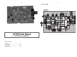
VU METER HOUSING (RIGHT)
3139 113 3513 pt4 dd wk0310
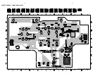
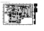
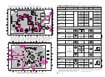
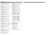
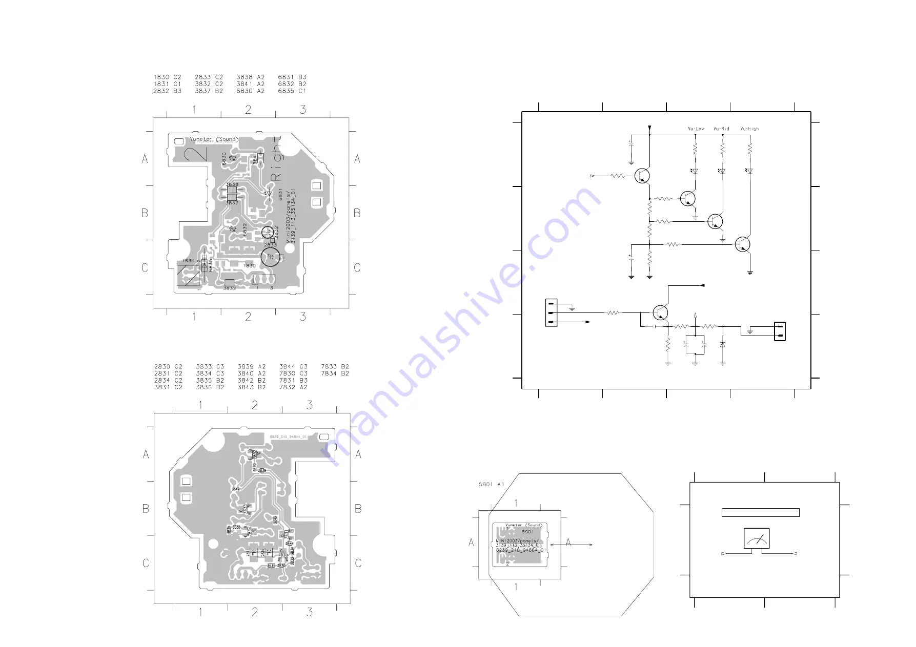
VU METER (RIGHT) BOARD - COMPONENT LAYOUT
VU METER (RIGHT) BOARD - CHIP LAYOUT
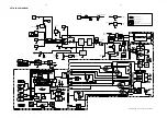
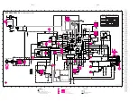
VU METER (RIGHT) BOARD - CIRCUIT DIAGRAM
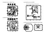
VU METER HOUSING (RIGHT) BOARD - COMPONENT LAYOUT & CIRCUIT DIAGRAM
5-7
5-7
Summary of Contents for FW-C557
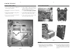
Page 10: ...Service position A Service position B Service position C 2 4 2 4 DISMANTLING INSTRUCTIONS ...
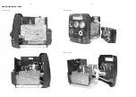
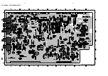
Page 37: ...8 3 8 3 AF11 BOARD CHIP LAYOUT MAPPING AF11 BOARD COMPONENT LAYOUT MAPPING ...
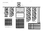
Page 60: ...10 8 Location of switches ...
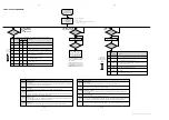
Page 66: ...10 14 10 14 Exploded view 5DTC mechanic for orientation only ...


