2-3
2-3
Repair Hints
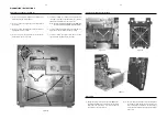
1) During repair it is possible to disconnect the ECO6 Tuner
board and/or 5DTC Module completely unless the fault is
suspected to be in that area. This will not affect the
performance of the rest of the set.
Dismantling of the Rear Panel assembly
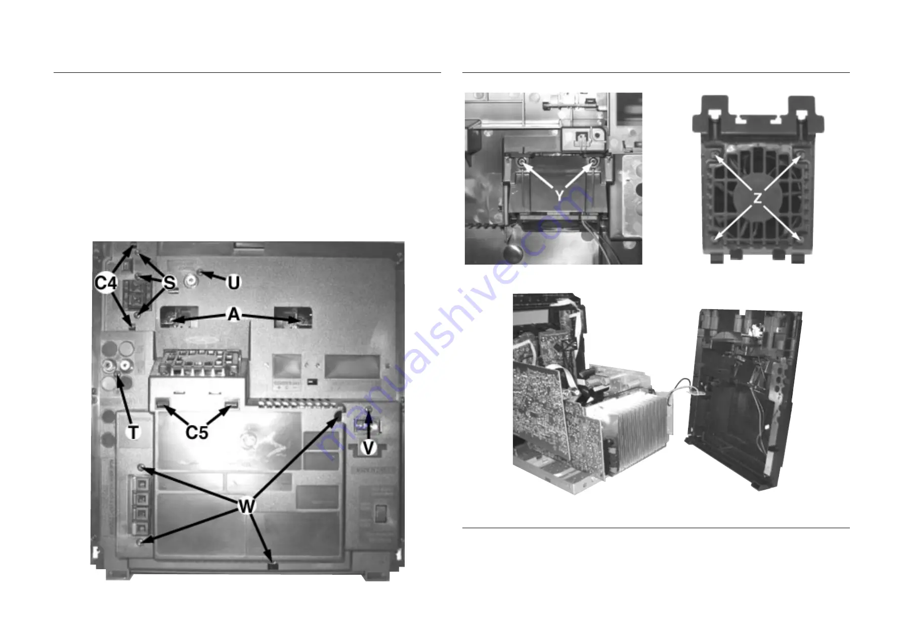
1) Loosen 3 screws S and 2 catches C4 (see Figure 16) to
remove the Tuner Board assembly.
2) Loosen 1 screw T (see Figure 16) to free the AF Board
(pos 1102-A).
3) Loosen 1 screw U (see Figure 16) to remove the Video
Cinch Out Board (pos 1102-B).
4) Loosen 1 screw V (see Figure 16) to free the Mains
Socket Board (pos 1106-1001-B).
DISMANTLING INSTRUCTIONS
Note: The flex cables are very fragile, care should be taken
not to damage them during repair. After repair, be
very sure that the flex cables are inserted properly
into the flex sockets before encasing, otherwise faults
may occurs.
5) Loosen 4 screws W (see Figure 16) and 2 catches C3
(see Figure 7) to remove the Panel Rear (pos 256) by
sliding it out towards the rear (see Figure 19).
Note : Tuner Board assembly and Mains Socket Board
can also be remove together with the Panel Rear.
6) Loosen 2 screws Y (see Figure 17) and 2 catches C5 (see
Figure 16) to remove the Bracket Fan (pos 266).
7) Loosen 4 screws Z (see Figure 18) to remove the Fan
(pos 1121) from the Bracket Fan (pos 266).
Figure 16
Figure 17
Dismantling of the Rear Panel assembly
Figure 18
Figure 19
Summary of Contents for FW-C557
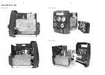
Page 10: ...Service position A Service position B Service position C 2 4 2 4 DISMANTLING INSTRUCTIONS ...
Page 37: ...8 3 8 3 AF11 BOARD CHIP LAYOUT MAPPING AF11 BOARD COMPONENT LAYOUT MAPPING ...
Page 60: ...10 8 Location of switches ...
Page 66: ...10 14 10 14 Exploded view 5DTC mechanic for orientation only ...


