10-1
TABLE OF CONTENTS
Servicing Hints ..................................................................10-2
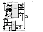
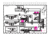
Blockdiagram ....................................................................10-5
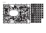
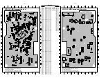
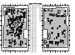
Component Layout Main Board ........................................10-6
Circuit Diagram part1 ........................................................10-7
Component Layout Main Board ........................................10-8
Circuit Diagram part2 ........................................................10-9
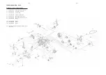
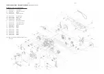
Exploded View ..................................................................10-10
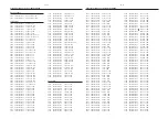
Partslist .............................................................................10-12
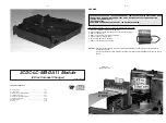
3CDC-LC-MB-DA11 Module
(3 Disc Carousel Changer)
Layout stage .2
10-2
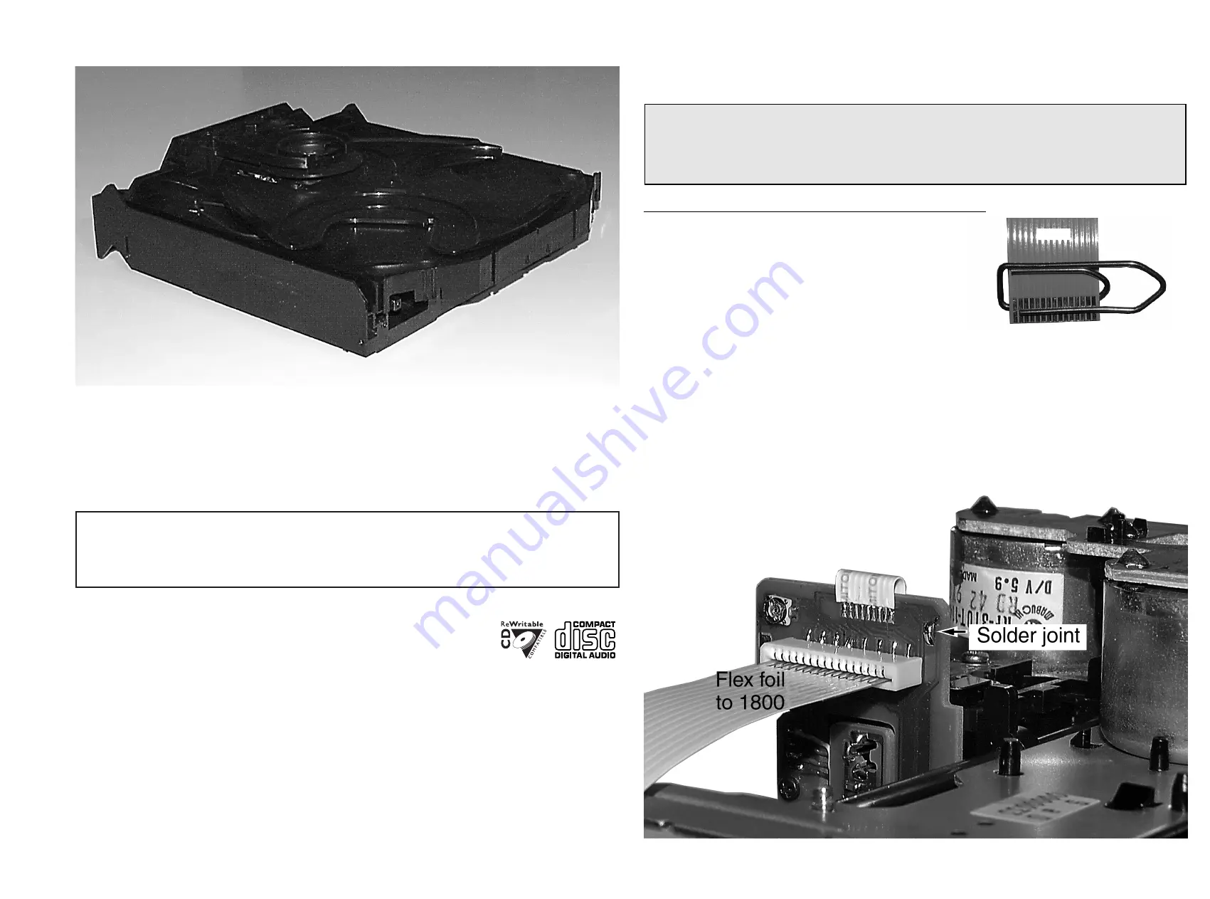
The following steps have to be done when replacing the CD mechanism:
1. Disconnect CD drive flexfoil from old CD drive
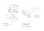
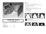
2. Connect paperclip to CD drive flexfoil to short-circuit flexfoil (fig.1)
3. Remove old CD drive
4. Remove short-circuit from flexfoil of CD drive
5. Connect flexfoil to new CD drive
6. Position new CD drive in its studs
7. Remove short-circuit from Laserunit
CHARGED CAPACITORS ON THE SERVO BOARD MAY DAMAGE THE CD DRIVE ELECTRONICS WHEN
CONNECTING A NEW CDM MECHANISM. THAT´S WHY, BESIDES THE SAFETY MEASURES LIKE
• SWITCH OFF POWER SUPPLY
• ESD PROTECTION
ADDITIONAL ACTIONS MUST BE TAKEN BY THE REPAIR TECHNICIAN.
WARNING
fig.1
Attention:
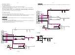
The laser diode of this CD drive is protected against ESD by a solder joint which shortcircuits the
laserdiode to ground.
For proper functionality of the CD drive this solder joint must be removed
after
connection the drive to
the set.
CD Drive
Bottom side view


