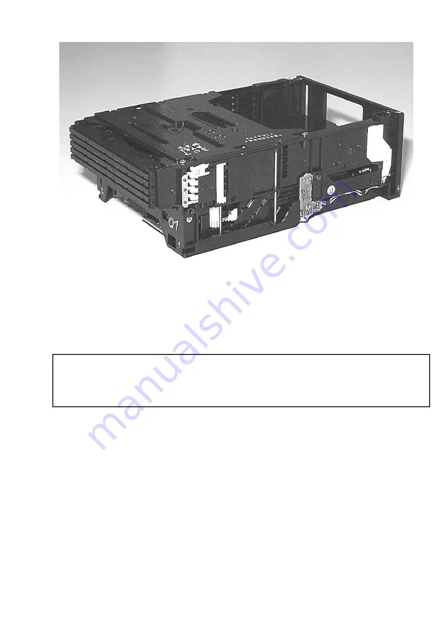
10-1
TABLE OF CONTENTS
Service hints ...............................................................................10-2
Location of Printed Circuit Boards ..............................................10-5
Wiring..........................................................................................10-6
Emergency opening ....................................................................10-7
Location of switches....................................................................10-8
Blockdiagram ..............................................................................10-9
CD B
OARD
Circuit Diagram .....................................................................10-10
Component Layout side A .....................................................10-11
Component Layout side B .....................................................10-12
C
ONTROL
B
OARD
Circuit Diagram .....................................................................10-13
Component Layout ...............................................................10-13
MP3 B
OARD
Circuit Diagram .....................................................................10-14
Component Layout ...............................................................10-15
Exploded view loader ...............................................................10-16
Partslist .....................................................................................10-17
5DTC Module
(MP3 version)
Layout stage .4
Summary of Contents for FW-M567
Page 10: ...Service position A Service position B Service position C 2 4 2 4 DISMANTLING INSTRUCTIONS ...
Page 41: ...8 3 8 3 AF11 BOARD CHIP LAYOUT MAPPING AF11 BOARD COMPONENT LAYOUT MAPPING ...
Page 64: ...10 8 Location of switches ...
Page 72: ...10 16 10 16 Exploded view 5DTC mechanic for orientation only ...


