The CD drive forms a compact building block with the CD Board.
The following steps have to be done when replacing the CD mechanism:
1. Desolder disc and slide motor
2. Loosen 2x screw
1. Disconnect flexfoil from old CD drive
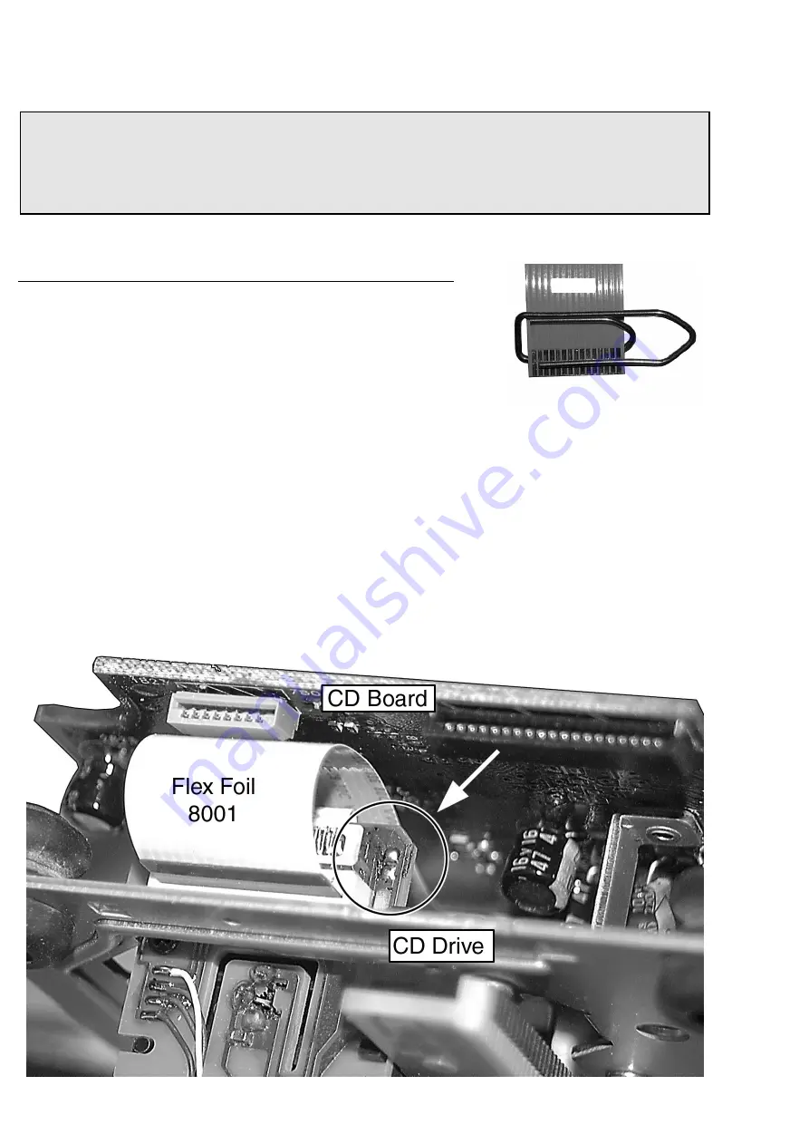
2. Put a paperclip over contacts of flexfoil to short-circuit the contacts (fig.1)
3. Remove old CD drive
4. Mount new CD drive to CD board
5. Solder disc and slide motor after fixing the drive to the board
5. Move slide outside
6. Remove paperclip from flexfoil
7. Connect flexfoil to new CD drive
8. Remove ESD-protection (solder joint) from laserunit (see picture below)
CHARGED CAPACITORS ON THE SERVO BOARD MAY DAMAGE THE CD DRIVE ELECTRONICS WHEN
CONNECTING A NEW CDM MECHANISM. THAT´S WHY, BESIDES THE SAFETY MEASURES LIKE
• SWITCH OFF POWER SUPPLY
• ESD PROTECTION
ADDITIONAL ACTIONS MUST BE TAKEN BY THE REPAIR TECHNICIAN.
10-4
WARNING
fig.1
Attention: The laser diode of this CD drive is protected against ESD by a solder joint which shortcircuits the
laserdiode to ground.
For proper functionality of the CD drive this solder joint must be removed after connection the drive to
the set.
Summary of Contents for FW-M567
Page 10: ...Service position A Service position B Service position C 2 4 2 4 DISMANTLING INSTRUCTIONS ...
Page 41: ...8 3 8 3 AF11 BOARD CHIP LAYOUT MAPPING AF11 BOARD COMPONENT LAYOUT MAPPING ...
Page 64: ...10 8 Location of switches ...
Page 72: ...10 16 10 16 Exploded view 5DTC mechanic for orientation only ...


