GB
CLASS 1
LASER PRODUCT
COMPACT
DIGITAL AUDIO
Service Manual
Service
Service
Service
FW-P900/
37
TABLE OF CONTENTS
Page
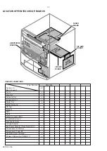
Location of pc boards & Version variations ................ 1-2
Technical Specifications ............................................. 1-3
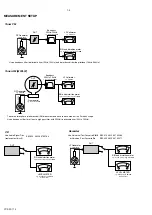
Measurement setup .................................................... 1-4
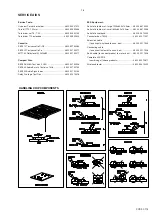
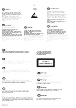
Service Aids, Safety Instruction, etc. .......................... 1-5
Instruction for use
................................................... 2-1
Disassembly Instructions & Service positions ........... 3-1
Service Test Programs ............................................... 3-4
Set Block diagram ......................................................... 4
Set Wiring diagram ........................................................ 5
Front Board .................................................................... 6
Tuner Board:
ECO5 Sys .......................................... 7B
ETF7 ND Tape Module .................................................. 9
3CDC-LC Module ........................................................ 10
3CDC-LC-MB Module ............................................... 10A
Power 5-VA Module (70/100W Version) ...................... 11
AF8 Board .................................................................... 12
DPL Board ................................................................... 13
Set Mechanical Exploded view & parts list ................. 14
©
Copyright 2000 Philips Consumer Electronics B.V. Eindhoven, The Netherlands
All rights reserved. No part of this publication may be reproduced, stored in a retrieval system or
transmitted, in any form or by any means, electronic, mechanical, photocopying, or otherwise
without the prior permission of Philips.
Published by BB 0039 Service Audio
Printed in The Netherlands
Subject to modification
Mini System
SPR 00 0102
3139 785 22540
For repair information on the Subwoofer, see Service Manual "SW900/17".
Summary of Contents for FW-P900
Page 20: ...D O N O T P R I N T B L A N K P A G E ...
Page 25: ...4 1 4 1 SET BLOCK DIAGRAM PCS 103 615 Blue Strip wOOx BassTreble ...
Page 44: ...PCS 103 378 9 6 9 6 COMPONENT LAYOUT CHIP LAYOUT 3 4 2 1 6 5 3 4 2 1 6 5 ...
Page 55: ...10 3 CS 53 302 Service Position ...
Page 56: ...10 4 CS 53 303 Wiring ...
Page 74: ...D O N O T P R I N T B L A N K P A G E ...
Page 101: ...14 1 14 1 SPR 00 0142 ...


