background image

6-5

6-5

SELECT/

OUTPUT
CIRCUIT

(BANK2: 8-BIT X 6 )

(BANK1: 8-BIT X 16)

CONTR

OL CIRCUIT

DOT DATA WRITE

CONTROL

REGISTER

CLOCK

GENERATOR

SEGMENT OUTPUT CIRCUIT

CGRAM

(35-BIT X 16)

SEGMENT/DIGIT

SEGMENT OUTPUT CIRCUIT

DISPLAY

DISPLAY

CODE

 WRITE

SERIAL

RECEIVE

CIRCUIT

DIGIT OUTPUT CIRCUIT

2

(35-BIT X 160)

CGROM

DISPLAY

CODE

RAM

CONTROLLER

CODE SELECT

CODE / COMMAND

I/O POR

TS

I/O PORTS

I/O PORTS

CPU

RAM

ROM

I/O POR

TS

STB

D

1

EN1

SRG8

8

9

10

11

12

6000  CD1

6001  CD2

6002  CD3

23x

WO

O

X

STDBY

-ON

I

1

2

3

4

5

6

7

8

9

10

11

12

13

14

15

1

2

3

10MHz

6004  AUX

6003  TUNER

4

5

6

7

13

14

15

A

B

C

D

E

F

G

H

I

A

B

C

D

E

F

G

H

150R

for FW

-R33:

provision

*

FTD 50 Pins

FTD 49 Pins

BLM21

BLM21

4x

BLM21

BLM21

BLM21

BLM21

BLM21

M24C02 to be used

provision

pro

vision

alternatively

only f

or FW

-R33

only f

or FW

-R55

MAX SOUND

4x

BLM21

*

*

(provision)

stuff

ed f

or FW

-R33

v

ersion detection:

provision

*

to be stuffed

10R

3068

3069

10R

3072

1K5

1K5

3071

220R

3059

220R

3060

3061

4K7

GP1U28XP

GND

3

MT

4

OUT

1

VSUP

2

7010

6012

3067

4K7

3066

6009

2K7

2035

D

6041

6040

BZX79-B9V1

3057

3056

3051

1R

D

10K

3054

3053

47R

3170

10K

3055

6038

6039

D

D

D

3043

3046

1K

3058

220R

1K

D

220R

3038

220R

3028

220R

3033

3036

220R

220R

3034

220R

3032

2K7

3104

4K7

3062

5011

5010

5009

20 XOUT

3R3

3144

3100

3R3

SEG26 33

SEG27 31

SEG28 30

SEG29 29

28

SEG30

SEG31 27

SEG32 26

SEG33 25

SEG34 24

SEG35 23

VCC1

19

VCC2

60

VP

32

VSS

22

XIN

21

SEG10

49

SEG11

48

SEG12

47

SEG13

46

SEG14

45

SEG15

44

SEG16

43

SEG17

42

SEG18 41

SEG19 40

SEG20 39

SEG21 38

SEG22 37

SEG23 36

SEG24 35

34

SEG25

61

DIG15

P0

18

P1

17

RESET_

13

SCK

15

SDATA

16

SEG00

59

SEG01

58

SEG02

57

SEG03

56

SEG04

55

SEG05

54

SEG06

53

SEG07

52

SEG08

51 50

SEG09

DIG00

12

DIG01

11

DIG02

10

DIG03

9

8

DIG04

DIG05

7

DIG06

6

DIG07

5

DIG08

4

DIG09

3

DIG10

2

DIG11

1

DIG12

64

DIG13

63

DIG14

62

M66005

7002

CS_

14

2024

100n

2u2

5013

BA

W56

6010

BA

W56

6008

GND

3

4

MT

OUT

1

VSUP

2

3123 270R

TSOP2836

7000

3049

22K

5008

2u2

10R

3048

6007

2K2

3018

1K5

3050

3047

10R

2036

4p7

100p

100p

2034

3159

3124 220R

220R

3026

7005
BC847B

3027

220R

220R

220R

3025

220R

220R

3023

3024

3022

220R

3021

220R

220R

220R

3029

3003

2K2

3010

5003

3042

1K

3041

1K

3040

1K

2K2

1K

3039

2K2

3007

3011

3006

2K2

100n

2031

3031

220R

2032

100n

3037

220R

3030

220R

5006

5004

5012

10u

2033

10u

2009

D

6035

BA

W56

6036

3086

6016

33K

6015

6031

6026

6024

6025

2K2

3019

3017

470R

470R

3162

3002

220R

3169

470R

6027

3005

D

2K2

6030

6029

220R

3191

6028

3013

220R

3192

3012

1K

1K

3008

3009

2K2

3186

150R

2K2

3185

150R

10n

2029

2010

2028

100n

2K2

3016

100n

3015

2K2

2K2

3014

6006

3197

47R

3196

7015
BC847B

2K7

3195

1K5

8 9

2030

10n

33 3 35 36 3

38 39

2 3

8 9

6

19

2

20 21 2 23 2 25 26 27 28 29

3

3 31 3

fwr55

10 1 1 13 1

15 16 17 18

1 2 3

5 6

9

5

50

6 7 8 9

1100

25 26 27 28 29 30 31 32 33 3 35 36 37 38 39

1 1 12 13 1

15 16 1 18 19 2

2 22 23 2

1101

fwr55

6032

6014

6033

6034

3136

220R

3139

220R

6020

6019

6018

220R

3115

6017

10K

5007

2u2

3128

6005

470R

3120

6023

6022

6021

3174

220R

2015

100n

100u

3179

220R

2016

3184

3183

220R

3181

220R

3182

47R

3178

220R

220R

220R

3180

220R

3177

3190

220R

2007

100u

3187

220R

3189

3188

220R

150R

PDZ-6.8B

6013

220R

3194

5002

3193

220R

220R

220R

3044

3035

220R

3088

220R

3020

220R

220R

3112

3087

3110

3113

220R

3108

220R

220R

220R

220R

3106

220R

3065

3091

220R

3121

3064

220R

220R

3135

2021

10u

220R

220R

3118

3117

220R

3131

3

5

6

7

8

9

1223

1

10

2

6

7

8

9

100p

2018

FE-BT-VK-N

1

10

11

12

13

1

15

16

2

3

5

1225

220R

3127

220R

3125

3176

220R

220R

3119

3175

220R

71

72

73

74

75

76

77

78

79

8

80

9

57

58

59

6

60

61

62

63

64

65

66

67

68

69

7

70

42

43

44

45

46

47

48

49

5

50

51

52

53

54

55

56

28

29

3

30

31

32

33

34

35

36

37

38

39

4

40

41

13

14

15

16

17

18

19

2

20

21

22

23

24

25

26

27

7001

M30625FGGP

1

10

11

12

2004

3105

100R

100n

5005

6037

BAV70

100n

2003

3151

3K9

100n

2008

2005

100u

330R

3111

2006

220R

100n

3089

220R

3090

220R

3045

470n

3146

27K

2013

10u

2022

3130

68K

10K

3171

1K

3079

2K2

3094

2K2

3138

3107

1K

1K

3084

1K

3074

6001

6003

6002

220R

3101

2K2

3140

2K2

3161

3114

1K

3116

2K2

2K2

3075

D

3093

2K2

3134

2K2

3160

470R

3085

2K2

2K2

3080

2K2

3109

470R

3158

M24C01

E0

1

E1

2

E2

3

6

SCL

SDA

5

VCC

8

4

VSS

WC_

7

7003

3147

2K2

470R

3148

2n2

2027

3145

470R

1K

3166

10K

3163

3150

3K9

100p

D

3133 220R

2012

100p

2020

3129 220R

2019

100p

10

1

16

8

100p

2017

3

2

15

4

5

6

7

14

13

12

11

9

74HC4094D

7004

32K768

15p

2002

3078

2K2

5001

2K2

3083

2001

15p

470R

3154

3092

2K2

2011

100p

3097 270R

3099

4K7

330R

3096

3098

1K5

7008

BC857B

3070

1K5

4018

100K

3167

220R

3137

3155

1K

3173

4K7

100R

3004

BC847B

7014

2026

100n

2025

7011

10n

3081

BC847B

7007

82K

82K

3001

BC847B

3122

470R

220R

3063

100n

2023

2K2

3052

5000

3095 470R

3164

220R

270R

3103

3168

220R

5

6

6000

1226

FE-BT-VK-N

1

2

3

3102 180R

BC847B

7006

82K

3000

100u

2000

6004

3156

100K

7012

P3_D

+FTD

FTD_RESET

FTD_RESET

+uPA

82K

3082

BC847B

HP_DET

FTD_CS

+5V6

LED_STR

LED_ON

LED DATA

LED_CLK

CD_DATA

NTC

I2C_DATA

I2C_CLK

CD_SWInfo

CD_STR

CD_CLK

CD_DATA

NTC

I2C_DATA

I2C_CLK

CD SWInfo

CD_STR

CD_CLK

F2

F1

-30V

+5V6

P4_D

CW_CLK

+EEProm

F1

F1_1

F2_1

LowPowerControl

MIC DET

RDS_D

A

T

A

CD_STR

CW_RESET

LED_D

A

T

A

CD_SWInf

o

LED_CLK

PWRDWN

I2C

CLK

KEY2

FTD_CLK

Pin60

-30L

CW_RESET

CW_CIREQ

+E

RESET

RC5

+RC5

CW

D

A

T

A

G3

Pin60

F_CNV

LED1

F2_1

LED_STR

F

TxD

I2C_D

A

T

A

KEY1

+5V6

F1_1

G8_B

P7

P8

P9

P21

P22

P23

P24

P25

P26

P27

P28

P29

P30

P31

P32

P33

P34

P35

P36

G6

G5

G4

G2

G1

+FTD

+FTD

NTC

-30L

+5V6_con

+5V6

+E

F

CNV

RESET

F

EPM

F

CE

F

RxD

F

CLK

F

R

TS

F

TxD

P1

P2

P3

P4

P5

P6

P5_D

P6_D

P1_D

P2_D

-30L

+5V6

+E

+E

+E

+uPA

+FTD

CD

CLK

+E

+5V6

+EEProm

+RC5

+uP

+E

+5V6_con

G9_B

KEY0

V

OL

B

P31_E

P30_E

P29_E

P28_E

P6_E

P7_E

P8_E

P9_E

P16_E

P10_E

P11_E

P12_E

P13_E

P14_E

P15_E

P17_E

P18_E

P22_E

P23_E

P24_E

P25_E

P26_E

P27_E

P19_E

G8_D

P20_E

P21_E

G9_D

G7_D

P7_D

P8_D

F_EPM

TU_STEREO

F_RTS

F_CLK

F_RxD

RESET

FTD_D

A

T

A

RC5

+uPA

CW_CLK

CW_CIREQ

RDS_CLK

CD

D

A

T

A

FTD_D

A

T

A

FTD_CLK

FTD_CS

CW_CLK

CW

D

A

T

A

+uP

WOOX

STDBY

G5_D

G4_D

F2_2

F1_2

LED_ON

JOG

A

V

OL

A

JOG_B

F1_2

F2_2

P36_E

P35_E

P34_E

P33_E

F_CE

TU_CE

TU_DATA

TU_CLK

P5

P6

P7

P8

P9

P10

P11

P12

P13

P14

P15

P16

P17

P18

P19

P20

P21

P22

P23

P24

P25

P26

P27

WOOX

LED3

STDBY

G1

P36

P35

P34

P33

P32

P31

P30

P29

P28

P22

P23

P24

P25

P26

P27

P36

P35

P34

P33

P32

P31

P30

P29

P28

G7

B

G8_B

G9_B

P1

B

P2

P3

P4

P16

P15

P14

P13

P12

P11

P10

P9

P1

P20

P19

P18

P17

P16

P15

P14

P13

P12

P11

P10

P32_E

+uPE

G6

G5

G4

G3

G2

P16_D

P17_D

P18_D

P19_D

P20_D

P21_D

P22_D

P23_D

P24_D

P25_D

P26_D

P27_D

P9_E

P31_E

P32_E

P33_E

P34_E

P35_E

P36_E

G1_D

-30V

G2_D

G1_D

P1_B

G7_B

P21

P20

P19

P18

P17

G7_D

G8_D

G9_D

P36_D

P35_D

P34_D

P33_D

P32_D

P31_D

P30_D

P29_D

P28_D

P1_D

P2_D

P3_D

P4_D

P5_D

P6_D

P7_D

P8_D

P9_D

P10_D

P11_D

P12_D

P13_D

P14_D

P15_D

P29_D

P28_D

G7_D

G8_D

G9_D

P1_D

P2_D

P3_D

P4_D

P5_D

P6_D

P7_D

P8_D

P9_D

P10_D

P11_D

P12_D

P13_D

P14_D

P15_D

P16_D

P17_D

P18_D

P19_D

P20_D

P21_D

P22_D

P23_D

P24_D

P25_D

P26_D

P27_D

G6_D

G3_D

G2_D

P30_E

P29_E

P28_E

P6_E

P7_E

P8_E

P11_E

P12_E

P13_E

P14_E

P15_E

P16_E

P17_E

P22_E

P23_E

P24_E

P25_E

P26_E

P27_E

P19_E

P20_E

P21_E

P36_D

P35_D

P34_D

P33_D

P32_D

P31_D

P30_D

P15_E

P16_E

P17_E

P18_E

P19_E

P20_E

P21_E

P18_E

G6_D

G5_D

G4_D

G3_D

P34_E

P33_E

P32_E

P31_E

P30_E

P29_E

P28_E

P22_E

P23_E

P24_E

P25_E

P26_E

P27_E

P35_E

P36_E

G1_D

G2_D

G3_D

G4_D

G5_D

+5V6

SPEED_LED

CW_DATA

CW_RESET

CW_CIREQ

CW CLK

CW DATA

+5V6

+E

+E

+RC5

LED4

P8

P7

P6

P8_E

P7_E

P6_E

+uPE

+uPE

F2

G6_D

-30L

P9_E

P10_E

P10_E

P11_E

P12_E

P13_E

P14_E

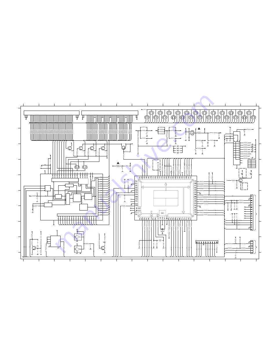
Disp ayFront Part1 2001 07 30

Display Front part1

T

o CDR Module

Flash connector

to Display Front part 2

T

o AF9 Board

1100 A1
1101 A4
1223 I13
1225 F15
1226 I15
2000 B15
2001 I9
2002 I9
2003 B11
2004 B13

2005 B12
2006 B11
2007 C12
2008 C12
2009 B8
2010 E7
2011 F14
2012 F14
2013 F1
2015 D7

2016 D7
2017 G14
2018 G1
2019 G14
2020 G14
2021 B8
2022 B10
2023 I1
2024 D2
2025 I1

2026 I1
2027 I5
2028 B13
2029 D10
2030 I14
2031 E7
2032 F7
2033 B10
2034 B14
2035 B14

2036 I9
3000 C4
3001 C4
3002 B4
3003 B4
3004 B15
3005 D10
3006 D10
3007 D11
3008 F12

3009 E12
3010 E12
3011 E12
3012 E12
3013 E12
3014 H11
3015 H9
3016 H9
3017 G12
3018 G12

3019 G12
3020 B5
3021 B6
3022 B6
3023 B6
3024 B6
3025 B6
3026 B7
3027 B7
3028 B7

3029 B6
3030 B6
3031 B6
3032 B6
3033 B6
3034 B6
3035 B5
3036 B7
3037 B7
3038 B7

3039 B7
3040 B7
3041 B7
3042 B7
3043 B7
3044 B5
3045 B5
3046 B7
3047 B8
3048 B10

3049 C8
3050 6
3051 B9
3052 D8
3053 G14
3054 G14
3055 B9
3056 B9
3057 A9
3058 B5

3059 B5
3060 B5
3061 E12
3062 E13
3063 B13
3064 B5
3065 B6
3066 D9
3067 C15
3068 B8

3069 B10
3070 C4
3071 C5
3072 C5
3074 H8
3075 E7
3078 H8
3079 H8
3080 H10
3081 C5

3082 C6
3083 F7
3084 H8
3085 H10
3086 B14
3087 B5
3088 B5
3089 B5
3090 B5
3091 B6

3092 F7
3093 D10
3094 F7
3095 C15
3096 C15
3097 C15
3098 C7
3099 C7
3100 B12
3101 C15

3102 C15
3103 C15
3104 D8
3105 B12
3106 B1
3107 H11
3108 B1
3109 H10
3110 B1
3111 C12

3112 B1
3113 B1
3114 H11
3115 B1
3116 H11
3117 B1
3118 B1
3119 B2
3120 D11
3121 B2

3122 H11
3123 B15
3124 I14
3125 B2
3127 B2
3128 I5
3129 F14
3130 F1
3131 B2
3133 F14

3134 F12
3135 B2
3136 B2
3137 F12
3138 F12
3139 B2
3140 F12
3144 D7
3145 D9
3146 G1

3147 H10
3148 D11
3150 I14
3151 I14
3154 D11
3155 I1
3156 I1
3158 D10
3159 I14
3160 D11

3161 H10
3162 I3
3163 H4
3164 I15
3166 I5
3167 I1
3168 I15
3169 I2
3170 I13
3171 H1

3173 I8
3174 B2
3175 B2
3176 B2
3177 B2
3178 B2
3179 B2
3180 B3
3181 B3
3182 B3

3183 B3
3184 B3
3185 B3
3186 B3
3187 B3
3188 B3
3189 B3
3190 B3
3191 B3
3192 B3

3193 B3
3194 B4
3195 E14
3196 E14
3197 E15
3232 H10
4018 B7
5000 H10
5001 I9
5002 B13

5003 A8
5004 A8
5005 B13
5006 A10
5007 D7
5008 C10
5009 B8
5010 B10
5011 B8
5012 B10

5013 D2
6000 C15
6001 C15
6002 C15
6003 C15
6004 C15
6005 6
6006 D15
6007 C11
6008 D4

6009 D15
6010 D4
6012 C11
6013 B12
6014 A10
6015 A10
6016 A11
6017 A11
6018 A11
6019 A12

6020 A12
6021 A12
6022 A12
6023 A13
6024 A13
6025 A13
6026 A14
6027 A14
6028 A14
6029 A14

6030 A15
6031 A10
6032 A10
6033 A9
6034 A9
6035 A9
6036 A8
6037 A11
6038 A15
6039 A15

6040 C11
6041 C11
7000 H4
7001 D12
7002 D2
7003 H3
7004 D14
7005 I5
7006 C4
7007 C3

7008 C7
7010 I4
7011 C5
7012 C6
7014 I1
7015 E15

4K7

3232

+E

4.6V

-22.4V

-22.4V

4.6V

5.4V

-26V

-22.4V

-22.4V

-23V

-33V

5.4V

4.8V

4.6V

-22.4V

-33V

4.8V

5.4V

-26V

-26V

4.8V

5.4V

-22.4V

-22.4V

-22.4V

-22.4V

-22.4V

-26V

-26V

5.4V

4.8V

-29V

-28.3V

5.4V

-26V

5.6V

4.8V

4.8V

4.8V

4.8V

Summary of Contents for FW-V320/21M

Page 1: ...ice Manual CDR Mozart Module 3122 785 60030 Technical specification 1 2 Measurement setup 2 1 RC 5 codes 2 2 Warnings Safety 2 3 Service Testprogram 3 3 Service Hints 3 1 Location of printed circuit boards 3 2 Dismantling Instructions 3 3 Service Testprogram 3 14 Wiring Diagram 4 1 Blockdiagram 5 1 Front Board 6 MICROPHONE BOARD 6 2 HEADPHONE BOARD 6 9 DIGITAL IN BOARD 6 9 CDR LIGHTGUIDE 6 9 3CDC ...

Page 2: ...ital Sound Control Input sensitivity Aux Line 500mV 2dB Microphone 2 5mV 2dB at 1kHz CDC unit Frequency response within 20Hz 20kHz at 1 5dB Signal Noise ratio 88dB A weighted Distortion at 1kHz 0dB 80dB Channel unbalance 0 3dB Channel crosstalk at 1kHz 75dB De emphasis 0 or 15 50 µS Laser Output power 500µW Wave length 780nm 20nm CDR unit CD Playback Frequency response within 20Hz 20kHz at 1 5dB S...

Page 3: ...22 707 48001 LF Voltmeter e g PM2534 DUT S N and distortion meter e g Sound Technology ST1700B Frame aerial e g 7122 707 89001 Tuner AM MW LW To avoid atmospheric interference all AM measurements have to be carried out in a Faraday s cage RF Generator e g PM5326 Ri 50Ω Low pass filter 22kHz L R LEVEL METER e g Sennheiser UPM550 with FF filter S N and distortion meter e g Sound Technology ST1700B D...

Page 4: ...mand Code 38 71 29 28 114 16 17 53 48 33 32 50 31 52 30 54 64 52 50 27 26 70 118 Remote control key Standby CD1 CD2 CD3 CDR Tuner Aux 1 ABC 2 DEF 3 GHI 4 JKL 5 MN 6 OPQ 7 RST 8 UVW 9 XYZ 0 Space YES NO EDIT TEXT PROGRAM PROGRAM TUNER MODE MUTE TIMER ON OFF System Code 17 20 21 26 20 20 20 26 17 21 17 20 21 26 17 20 21 26 17 20 21 26 17 20 21 26 17 20 21 26 17 20 21 26 17 20 21 26 17 20 21 26 17 20...

Page 5: ... which are identical with those specified be used Safety components are marked by the symbol i Le norme di sicurezza estigono che l apparecchio venga rimesso nelle condizioni originali e che siano utilizzati i pezzi di ricambiago identici a quelli specificati Componenty di sicurezza sono marcati con ñ Veiligheidsbepalingen vereisen dat het apparaat in zijn oorspronkeliijke toestand wordt teruggebr...

Page 6: ...onents The sets are equipped with a special DEALER MODE This mode blocks the trays of the CDC and CDR module to prevent customers from fetching out CDs from exhibition sets The dealer mode can be switched on off as follows 1 Switch the set with the stanby button to standby mode 2 Press the DISPLAY key for longer than 5s Display shows TRAYS LOCKED respectively UNLOCKED Escape from Dealer Mode The d...

Page 7: ...le Combi Board Power Module Mains Board AF9 Board 3CDC Keys CDR Lightguide FW R55 Locationof Printed Circuit Boards 2001 04 12 Location of Printed Circuit Boards Attention CDR Lightguide 3CDC Key Board Digital In Board Microphone Board and Headphone Board are part of the Front Board ...

Page 8: ...3 3 picture 1 DISMANTLING INSTRUCTIONS Dismantling the Top Cover Remove 4 screws as shown in picture 1 Raise top cover at the rear and pull it backwards as shown in picture 2 picture 2 ...

Page 9: ...3 4 picture 3 picture 4 DISMANTLING INSTRUCTIONS Dismantling the Side Cover Remove 3 screws for each side as shown in picture 3 Remove side cover as shown in picture 4 ...

Page 10: ...ase of a Supply fault the tray can be opened manually Turn gearwheel clockwise as shown in picture below Remove the 3CDC Tray cover To release the cover from the catch on the tray pull it frontwards on bottom side as shown in picture 5 Pull the cover up picture 5 ...

Page 11: ...3 6 picture 7 picture 6 Dismantling the 3CDC Module continued Remove 2 screws on front side first see picture 6 Remove 2 screws on back side see picture 7 DISMANTLING INSTRUCTIONS ...

Page 12: ...3 7 DISMANTLING INSTRUCTIONS Repair position for the 3CDC Module ...

Page 13: ...antling the CDR Module Remove 3CDC module first see previous pages Remove CDR Tray cover see picture 8 In case of a Supply fault the tray can be opened manually Use a screwdriver to release the tray as shown in picture below picture 8 ...

Page 14: ...3 9 DISMANTLING INSTRUCTIONS Dismantling the CDR Module continued Remove 2 screws on front side first see picture 9 Remove screws on the left and the right side see picture 10 picture 9 picture 10 ...

Page 15: ...connect all wires and remove the module Loosen screws shown in picture 11 and remove the top cover picture 11 Repair position for the Mozart Module Connect Power Front AF9 Board and 3CDC Module to get an operating CDR Module Power supply Front Board 3CDC Module AF9 Board ...

Page 16: ...picture 12 to get access to the other side or to dismantle the Mozart Board Repairs on Basic Engine Remove Mozart Board as described before Open the tray Remove 4 screws as shown in picture 13 to dismantle the module from the metal box This is necessary to get access to the Basic Engine picture 12 picture 13 ...

Page 17: ...3 12 Repair position for the CDR Module Basic Engine Connect Power Front AF9 Board and 3CDC Module to get an operating CDR Module DISMANTLING INSTRUCTIONS ...

Page 18: ...apter 3 5 to 3 7 Release two catches see picture 14 Remove 3 screws see picture 14 DISMANTLING INSTRUCTIONS Repair position for the Power Board Place the AF9 board on the CDR Module as shown in picture below Use a sheet of cardboard inbetween to avoid shortcircuits picture 14 ...

Page 19: ...Display shows ERR Display shows Testpattern is written to an address and read back again PROGRAM button pressed STOP button pressed Test ok N Y N Y This test should only be used to clear the EEPROM in case of a µP hangup Attention all data are set to default values BLACK BOX data are not cleared DISPLAY button pressed DISPLAY button pressed N N Y Fig 1 Y Display shows all segments and flags in dim...

Page 20: ...nside Inner switch or slide motor problems W E1020 Focus Search Error Triggered when he focus could not be found wi hin 4s when starting up the CD F W W E1001 Radial error Triggered when he radial servo is not on track for a certain time during playing the CD W W W W W Warning F Fatal Error set stops operation message remains on the display CD ERROR CODES table 1 E1005 Jump error Triggered when th...

Page 21: ...Tray closes PLAY button pressed N N Y FOCUS TEST PLAY button pressed N Y Dependent on the moving direction slide moves to inner or outer end position Exit Mech Testprogram YES button pressed N Y TURNTABLE TEST YES button pressed N Y Display shows DISC Turntable motor is switched on Turntable motor is switched on Objective moves continuously up down Display shows FOCUS Focus servo is switched off s...

Page 22: ...minutes ss remaining seconds STOP button pressed Exit DC ERASE Mode Note With the DC Erase mode the CD RW can be changed back in its original state l ke a new disc Stopping the erase function by switching power off will leave the disc in an unpredictable status CD RW disc inserted ERASE button pressed N Y CDR DC ERASE MODE Insert CD DA disc before starting the test N Y Plug mains cord off to exit ...

Page 23: ...GND_D VOL_B GND_D GND_D LED4 5V6 LED1 GND_D JOG_B JOG_A VOL_A GND_D VOL_B GND_D KEY_1 KEY_0 E E GND_D GND_D GND_D KEY_2 GND_D LED3 5V6 GND D LED4 GND_D F_TxD F_CNV RESET GND_D F_EPM F_CE F_RxD F_CLK F_RTS E GND_D AMP_left GND_A AMP_right NTC Low Power Control POWER DOWN Clipping AMP ON Vkk F1 F2 Ampl_CS_DC VCD_ON CDR_ON Low Power supply 12V_A GND_A 12V_M GND_M 5V6 GND_D Power down SA_IN MIC DET Cl...

Page 24: ...nnected not connected ANALOG IN REC L ANALOG IN REC R ANALOG OUT PB R ANALOG OUT PB L IRQ 1214 1 6 5V 5V 12V 3 1 CD CHANGER MODULE for details see Chapter 10 8 1 EBU PORE SDA SICL RAB SILD 1802 1805 9 1 SW Info SHR STR SHR CL SHR DATA 5V NC NC 10V AF 9 BOARD for details see Chapter 8 IS IS BASS ALC L R ALC CONTROL SOURCE SELECTOR VOLUME I I2 C Control SOUND VOLUME II FADER I2 C Control D7 D6 D5 D4...

Page 25: ...omponent Layout Copperside 6 4 Circuit Diagram part1 6 5 Component Layout Componentside 6 6 Circuit Diagram part2 6 7 JOG FRONT Circuit Diagram 6 7 Component Layout 6 8 Break away parts 6 9 Display pinning 6 10 Partslist 6 11 Front Board Layout stage 3 Display Front Jog Front ...

Page 26: ...3402 2405 E B C 7400 E B C 7401 E B C Microphone Board FW R55 2001 06 08 Microphone Board 4 5 6 7 1 A B C D E 2 3 MIC_DET B C D E 1 2 3 8 9 10 5 6 7 provision 4 A GND_A 8 9 10 180R 3410 11V_A GND_A MIC 100n 2404 2403 10u 2406 1n 3404 2K7 6K8 3411 470R 3416 11V_A 2K2 3402 3415 1K 1M 3403 1n 2407 3409 2401 470u 4n7 2408 22R RK09D 3400 20K 2 3 1 5 4 7402 BC847B 11V_A 3413 10K 100K 3417 2K7 3405 2400 ...

Page 27: ... TU_DATA TU_CE FTD RESET STB D EN1 SRG8 10 1 16 8 3 2 15 4 5 6 7 11 13 12 14 9 74HC4094D 7004 5V6 LED_STR LED ON LED_DATA LED_CLK LED_ON LED_STR LED_DATA LED_CLK OSC LED4 LED1 TUNER CD2 CD3 CD1 AUX SPEED 2x RED BLUE YES 5V6 LED3 7300 SPEED LED TU STEREO TU CLK TU DATA TU_CE F_TxD F_CNV F EPM F CE F RxD F RTS F CLK RESET RDS_CLK RDS_DATA RDS CLK RDS DATA 7600 7601 GP1U28XP 7000 or 7010 RC5 uP uPA F...

Page 28: ...110 B10 3111 C5 3112 A10 3113 A10 3114 B4 3115 A10 3116 A4 3117 A9 3118 A9 3119 A9 3120 C5 3121 A9 3122 B4 3124 D4 3125 A9 3127 A9 3128 D5 3129 B2 3130 B7 3131 A9 3133 B3 3134 B4 3135 A9 3136 A9 3137 B4 3138 B4 3139 A9 3140 B4 3145 D4 3146 C8 3147 A4 3148 C5 3150 E4 3151 E4 3154 C4 3155 D2 3156 D3 3158 D4 3159 D4 3160 C4 3161 A4 3162 B6 3163 C10 3164 E6 3166 B10 3167 D2 3168 E6 3169 B5 3171 B4 317...

Page 29: ... P4_D CW_CLK EEProm F1 F1_1 F2_1 LowPowerControl MIC DET RDS_DATA CD_STR CW_RESET LED_DATA CD_SWInfo LED_CLK PWRDWN I2C CLK KEY2 FTD_CLK Pin60 30L CW_RESET CW_CIREQ E RESET RC5 RC5 CW DATA G3 Pin60 F_CNV LED1 F2_1 LED_STR F TxD I2C_DATA KEY1 5V6 F1_1 G8_B P7 P8 P9 P21 P22 P23 P24 P25 P26 P27 P28 P29 P30 P31 P32 P33 P34 P35 P36 G6 G5 G4 G2 G1 FTD FTD NTC 30L 5V6_con 5V6 E F CNV RESET F EPM F CE F R...

Page 30: ...B6 3100 B3 3102 A2 3103 A2 3105 D11 3123 B2 3144 C10 3170 D2 3202 E8 3204 E3 3205 A3 3206 E2 3211 D4 3214 D11 3215 E10 3218 E6 3219 E4 3221 E5 3223 E3 3225 D3 3229 B3 5000 A4 5001 A4 5007 C8 5008 A11 5013 A7 5200 A3 6000 A2 6001 A2 6002 A2 6003 B2 6004 B2 6005 A12 6006 C3 6007 B11 6009 C3 6012 C11 6040 B11 6041 C11 7000 B10 7010 B10 9001 A10 9002 A10 9003 A10 9004 A8 9005 A8 9006 A7 9007 A6 9008 A...

Page 31: ...12 3344 10K 10n 2311 10n 3345 10K 2310 L L 3311 47R 3310 1K5 LTL 053 6301 BC847B 7300 9350 D 1K 3307 2307 10n D 3316 1K D EC16 1331 1 2 3 4 5 3342 1K 10K 3317 3318 11 12 2 3 4 5 6 7 8 9 10K FFC 1320 1 10 E E E E E SPEED SPEED Jog Front OPEN CDR FINALIZE REC TYPE DSC CD TEXT VAC EDIT STOP ERASE PROG NO 1311 820R 3319 560R 1300 3313 1302 1308 3303 220R 1K8 1K2 3323 1315 3330 390R 3306 1316 10K 3346 ...

Page 32: ...10 D6 1311 D9 1312 E8 1314 D7 1315 D9 1316 C9 1317 C8 1318 C7 1319 C6 1320 C9 1330 D3 1331 D8 1350 D3 2307 D3 2308 D3 2310 D8 2311 D8 3303 D9 3304 D9 3305 C8 3306 E8 3307 D8 3308 C7 3309 D5 3310 D8 3311 D8 3312 C8 3313 E7 3314 D7 3316 C8 3317 C8 3318 C8 3319 E6 3321 D7 3323 E5 3326 D6 3330 E3 3339 D5 3340 D2 3341 D5 3342 C8 3343 C8 3344 C8 3345 C8 3346 B2 4302 C9 6300 C7 6301 C6 7300 D8 9300 C8 93...

Page 33: ...vision HP_DET provision 2701 22n 2700 22n 2u2 5700 5702 2u2 HP 100n 2703 9700 22n 2702 2u2 5701 9 8 7 1 2 3 4 5 6 FFC 1 2 3 4 1701 TC38 1702 1700 HEADPHONE BOARD To AF9 Board Copperside view 3809 3809 3807 3807 FW R55 D gi al Sw tch Board Layout stage 3 2001 06 07 DIGITAL IN BOARD Componentside view Chip Components FW R55 Led Board Layout stage 3 2001 06 07 LIGHTGUIDE BOARD Copperside view Compone...

Page 34: ... 1c 1e 1r 1n 1d 2a 2h 2j 2k 2b 2f 2m 2g 2c 2e 2r 2n 2d TIME TRACK 3G EDIT TEXT CD 1a 1h 1j 1k 1b 1f 1m 1g 1c 1e 1r 1n 1d 2a 2h 2j 2k 2b 2f 2m 2g 2c 2e 2r 2n 2d REM TOTAL 2G TRACK Dot Colon 1a 1h 1j 1k 1b 1f 1m 1g 1c 1e 1r 1n 1d 2a 2h 2j 2k 2b 2f 2m 2g 2c 2e 2r 2n 2d TRACK REC 1G 1p PM AM 1a 1h 1j 1k 1b 1f 1m 1g 1c 1e 1r 1n 1d 2a 2h 2j 2k 2b 2f 2m 2g 2c 2e 2r 2n 2d Dot TIME PM AM TRACK EDIT CD TEXT...

Page 35: ...305 100nF 10 16V 2005 4822 124 41584 100µF 20 10V 2006 4822 126 14305 100nF 10 16V 2007 4822 124 41584 100µF 20 10V 2008 4822 126 14305 100nF 10 16V 2009 4822 124 40248 10µF 20 63V CAPACITORS 2010 4822 126 14305 100nF 10 16V 2011 4822 122 31765 100pF 5 50V 2012 4822 122 31765 100pF 5 50V 2013 3198 017 44740 470nF 20 10V 2015 4822 124 41584 100µF 20 10V 2016 4822 126 14305 100nF 10 16V 2017 4822 12...

Page 36: ...2kΩ 5 0 6W 3082 4822 117 12864 82kΩ 5 0 6W 3083 4822 051 30222 2 2kΩ 5 0 06W 3084 4822 050 11002 1kΩ 5 0 2W RESISTORS 3085 4822 051 30222 2 2kΩ 5 0 06W 3086 4822 051 30333 33kΩ 5 0 06W 3087 4822 051 30221 220Ω 5 0 06W 3088 4822 051 30221 220Ω 5 0 06W 3089 4822 051 30221 220Ω 5 0 06W 3090 4822 051 30221 220Ω 5 0 06W 3091 4822 051 30221 220Ω 5 0 06W 3092 4822 051 30222 2 2kΩ 5 0 06W 3093 4822 051 30...

Page 37: ...kΩ 5 0 06W 3227 4822 051 30221 220Ω 5 0 06W RESISTORS 3228 4822 117 11817 1 2kΩ 1 0 06W 3229 4822 050 11002 1kΩ 5 0 2W 3232 4822 051 30472 4 7kΩ 5 0 06W 3233 4822 051 30684 680kΩ 5 0 06W 3303 4822 116 83872 220Ω 5 0 5W 3304 4822 116 83876 270Ω 5 0 16W 3305 4822 116 83876 270Ω 5 0 16W 3306 4822 116 83881 390Ω 5 0 5W 3308 4822 116 83881 390Ω 5 0 5W 3312 4822 050 11002 1kΩ 5 0 2W 3313 4822 116 52226 ...

Page 38: ...W56 6016 5322 130 30691 BAW56 6017 5322 130 30691 BAW56 6018 5322 130 30691 BAW56 6019 5322 130 30691 BAW56 6020 5322 130 30691 BAW56 6021 5322 130 30691 BAW56 6022 5322 130 30691 BAW56 6023 5322 130 30691 BAW56 6024 5322 130 30691 BAW56 6025 5322 130 30691 BAW56 6026 5322 130 30691 BAW56 6027 5322 130 30691 BAW56 6028 5322 130 30691 BAW56 6029 5322 130 30691 BAW56 6030 5322 130 30691 BAW56 6031 5...

Page 39: ...ab B V Stab B V Stab A V Stab B 10 7 MHz 10 7 MHz 35 9 Vdd Vcc1 7 23 V Stab A V Stab B 38 34 22 Vcc2 8 ECO6 Systems Cenelec 140499 V Loop FM AM RF AM Osc FM IF 1 FM IF 2 LF filter MPX buffer ampl RDS MPX 5 RDS MPX stereo clock data enable Version 3 1120 AM IF 1 AM IF 2 AM AFC 1 8 AM Frontend 2 AM FRAME AERIAL B 1103 1101 1102 A FM AM FM Discriminator 10 7 MHz Vdd FM Vcc1 Vcc Vcc2 MW LW AM RF AM Os...

Page 40: ... 22n USA 22n USA C PAD 1131 T141 2106 11p 20p_LW 0R 4104 0R 41xx 2165 100n 1130 C PAD 10K 3180 2150 100n BZX284 C11 6107 T102 2127 220n 2169 2n2 100K 3170 1 I 3 O 2125 560p 5109 2 G 470R 3152 2108 100p 3125 10K 3153 470R 330R 3193 T103 120R 3167 100R 3195 7 8 33K 3176 8 5122 1 2 3 4 6 5123 1 2 3 4 6 7 5110 G 2 I 1 O 3 5115 1 2 3 4 6 7 8 2 3 4 6 7 8 5119 1 2135 100n 2163 LW 7104 BC337 40 2145 220p ...

Page 41: ...e Testprogram By selecting the TUNER TEST test frequencies will be stored as preset frequencies automatically AM FRAME AERIAL FM 75Ω FM FRONTEND Birdy Filter ECO6 Sys Cenelec layout stage 6 160501 1101 B5 1102 B5 1103 C5 1110 B4 1120 A4 1130 A5 1131 C5 1132 A4 2106 B4 2107 B3 2128 A3 2129 B3 2133 C1 2138 B1 2144 B1 2162 A4 2191 B4 3142 C2 5102 C4 5103 C4 5109 B3 5110 A2 5111 A3 5112 A2 5114 A2 511...

Page 42: ...198 021 38210 820Ω 5 0 06W 3132 4822 051 20479 47Ω 5 0 1W 3134 4822 051 20223 22kΩ 5 0 1W 3135 3198 021 31020 1kΩ 5 0 06W 3137 4822 051 20223 22kΩ 5 0 1W LW only 3141 4822 117 11148 56kΩ 1 0 1W 3142 4822 100 12159 TRIMPOT 100kΩ 3143 4822 051 20223 22kΩ 5 0 1W RDS only 3144 4822 051 10102 1kΩ 2 0 25W RDS only 3145 4822 117 11449 2 2kΩ 1 0 1W 3146 4822 051 20229 22Ω 5 0 1W 3150 4822 117 10833 10kΩ 1...

Page 43: ... DOLBY PRO LOGIC DPL INTERFACE The AF9 Board has provisions which can be configured to cater for DPL d LINE OUT Line out cinch socket for connection to external amplifier e SUB WOOFER OUT Sub woofer out cinch socket for connection to active sub woofer speaker f INCREDIBLE SURROUND Incredible surround effect using transistor circuit to create phase shifting and spatial effect g HEADPHONE AMPLIFIER ...

Page 44: ... AF9 BOARD COMPONENT LAYOUT This assembly drawing shows a summary of all possible versions For components used in a specific version see schematic diagram and respective parts list 3139 113 3435 pt4 dd wk0123 ...

Page 45: ...8 3 AF9 BOARD CHIP LAYOUT This assembly drawing shows a summary of all possible versions For components used in a specific version see schematic diagram and respective parts list 3139 113 3435 pt4 dd wk0123 ...

Page 46: ...GND_A 3561 1K 47K 3544 220u 2204 A_M c 3501 4K7 1n8 2552 A_Aux 3572 A_Tp 12K 3504 4920 GND_EMC A_Tp 470n 2594 GND_A 9654 680K 3565 3K3 3547 470n 2666 470p 8K2 3555 GND_A A_Aux 220K 3568 3532 1K5 A_HP 470p 2665 2n2 2205 2589 1K 3690 SUB_W 27K 3533 220n BC817 25 7693 17 14 15 9 20 1 2697 470p 13 28 3 26 4 25 5 24 6 23 8 21 2 7 22 12 TDA7468 7501 16 10 19 11 18 27 GND_A 3699 470R 1510 FE BT VK N 1 2 ...

Page 47: ...2 GND 8 SCL 2 SDA 3 SO 1 VDD 13 7403 M62320FP 16 CS0 CS1 15 CS2 14 D0 4 5 D1 D2 6 5V_VCD 9402 GND_D GND_D 5V_CD 2401 100p 100p 2402 5V_CD 470R 3402 9401 3711 5K6 5V6 2R2 3410 BC327 25 7401 7402 GND_D 5K6 3409 GND_D VCD_ON BC847B 2K2 3694 10K 3408 GND_D 5V 5V6 100n 2404 100R 3403 1K 3619 GND_D 2403 100n 2624 22n 22u 2612 3627 10R 2623 47u 5621 2u2 MUTE_SW 1K 3658 100p 2654 7652 BC817 25 3657 1K 265...

Page 48: ... 6205 Pw_Dn 1204 EH B 1 2 3 4 5 6 7 47u 2207 7404 BC817 25 6209 BZX79 C6V8 12V_M 4913 NTC GND_D GND_D GND_D 1N4003 AMP_CS_DC 4 5 6 7 8 9 TU_Right Vkk 5V_CD 47u 2209 GND_D GND_D 3821 10R 100n 2211 A_TU 6207 1N4003 3822 270R 10 11 12 13 14 15 16 2 3 4 5 6 7 8 9 5V 1405 1 GND_D GND IN OUT 3820 10R P provision 3139 118 53770 88340 for 3435 pt4 dd wk0123 Note Some values may varies see respective parts...

Page 49: ...22 126 14305 100nF 10 16V 2522 4822 126 14305 100nF 10 16V 2523 4822 122 31765 100pF 2 63V 2524 4822 122 31765 100pF 2 63V 2531 4822 124 40769 4 7µF 20 100V 2532 4822 124 40769 4 7µF 20 100V 2533 4822 122 31765 100pF 2 63V 2534 4822 122 31765 100pF 2 63V 2535 4822 124 40769 4 7µF 20 100V 2536 4822 124 40769 4 7µF 20 100V 2541 4822 124 41407 0 47µF 20 63V 2542 4822 124 41407 0 47µF 20 63V 2543 5322...

Page 50: ...22 051 30471 470R 5 0 062W 3668 4822 051 30472 4k7 5 0 062W 3669 4822 051 30103 10k 5 0 062W 3690 4822 051 30102 1k 5 0 062W 3694 4822 051 30222 2k2 5 0 062W 3699 4822 051 30471 470R 5 0 062W 3700 4822 051 30332 3k3 5 0 062W 3707 4822 051 30102 1k 5 0 062W 3708 4822 051 30102 1k 5 0 062W 3711 4822 051 30562 5k6 5 0 063W 3820 4822 116 52176 10R 5 0 5W 3821 4822 052 10109 10R 5 0 33W 4100 4822 051 3...

Page 51: ... as so called super class G amplifiers The supply pins 12 Vcc are not just connected to one fixed DC supply as in conventional amplifiers Dependent on the output power there are three different DC voltages supplied to the power amplifiers C1 20V for low output power B1 29V for medium output power A1 41V for high output power Principle benefit of Super Class G Conventional power stage Class G ampli...

Page 52: ...eration of A1 Common full wave rectifying with bridge rectifier 6202 using 100 secondary winding of mains transformer pin 10 14 Generation of B1 The supply for B1 consists of one full wave rectifier 2 diodes of bridge rectifier 6202 with 6200 6220 in parallel 6201 6221 in parallel for generation of B1using approx 70 secondary winding of mains transformer pin 10 13 respectively pin 11 14 As example...

Page 53: ...sed for monitoring the transformer temparature LOW_PWR_SUP is used to supply the microprocessor during ECO stand by is used for filament of display Vkk supply of display supply for Power amplifier Super Class G LEFT RIGHT from Source Selector on Audio Frequency Board 6210 6214 5203 Stand by Transformer B1 LOW_PWR_CNTRL C1 5V6 5V_VCD VCD_ON 7330 VCD_ON Blockdiagram Power2001 30 70W 26 09 2000 12V R...

Page 54: ... C5 6213 B5 6214 B5 6215 D5 6216 C5 6217 C5 6218 C5 6220 B3 6221 B3 6222 B5 7200 A2 7201 D5 7202 C5 7203 A3 9206 B2 9208 B1 9210 D1 9211 D4 9212 D5 9213 D4 9214 C5 9216 B4 9217 B3 9218 C4 9219 C1 9220 C3 9221 D3 9222 D3 9223 C4 9224 B4 9225 B4 9226 D4 9227 B4 9228 D3 9229 C5 9230 C3 9231 D3 9232 D2 9233 D3 9234 D2 9235 C3 9236 C3 9237 C3 9238 C3 9239 C3 9240 C2 9241 C2 9242 B5 9243 A4 9244 A5 9245...

Page 55: ...4K7 3205 5203 1 10 5 6 8 BZX79 C33 6207 6201 1N5392 1N5392 6220 6221 1N5392 T5A 1200 19372 1N4003 6214 4m7 2217 C1 9214 3211 4R7 5202 97TS 6 7 8 9 11 12 13 14 15 16 17 2 3 4 5 5001 1 10 6m8 2216 6206 1N4003 T1 6A 1208 4K7 3208 3207 4K7 NTC F1 ECO F2 NTC LOW_PWR_SUP LOW_PWR_SUP LOW_PWR_SUP ECO F2 F1 not on all versions not on all versions Mains Transformer Voltage Selector Stand by Transformer Stan...

Page 56: ...3392 B1 3393 C2 3394 C1 3395 C2 3396 A1 3397 C2 3398 A4 5300 A5 5301 B5 5302 A5 5303 B5 6300 B5 6301 C5 6302 B5 6303 C5 6304 C4 6305 C2 6306 B3 6307 B4 6308 B3 6309 A3 6310 A4 6311 B3 6312 B3 6313 A2 6314 B3 6315 C3 6316 A2 6317 A4 6318 A3 6319 A3 6320 B2 6321 B1 6322 C2 6323 C4 6324 C4 6325 A1 6326 A1 6327 A1 6328 C1 6329 B1 6330 A1 6331 A3 6332 A3 6333 C1 6334 A1 6335 C3 7300 A4 7301 C4 7302 A4 ...

Page 57: ...306 E1 1307 a F14 1307 b E14 1308 F12 1310 G1 1312 H1 1313 I9 1314 G1 1315 D1 1316 D1 2300 E8 2301 B7 2302 F7 2303 B7 2304 G7 2305 B8 2306 G7 2307 D8 2308 H8 2309 B9 2310 F9 2311 B10 2312 F10 2313 C10 2314 G10 2315 D9 2316 H9 2317 F13 2318 F13 2319 F13 2320 F13 2321 F14 2322 F13 2323 A4 2324 B14 2325 A5 2326 B3 2327 B6 2328 D4 2329 E5 2330 E5 2331 E6 2332 F5 2333 G7 2334 H6 2335 H5 2336 E4 2337 F4...

Page 58: ...4822 116 52283 4 7kΩ 5 0 5W 3327 4822 116 52213 180Ω 5 0 5W 3328 4822 050 11002 1kΩ 5 0 2W 3329 4822 053 11221 220Ω 5 2W 3330 4822 053 11221 220Ω 5 2W 3331 4822 050 23303 33kΩ 1 0 6W not for CDR 3331 4822 116 52269 3 3kΩ 5 0 16W for CDR only 3332 4822 116 52256 2 2kΩ 5 0 16W 3333 4822 116 52199 68Ω 5 0 16W 3336 4822 050 21003 10kΩ 2 0 25W 3337 4822 116 52206 120Ω 5 0 5W 3338 4822 116 52176 10Ω 5 0...

Page 59: ...Blockdiagram 10 5 Component Layout Main Board 10 6 Circuit Diagram part 1 10 7 Component Layout Main Board 10 8 Circuit Diagram part 2 10 9 Circuit Diagram part 3 10 10 Exploded View 10 10 Partslist 10 12 3CDC LC CDR 3 Disc Carousel Changer Layout stage 6 ...

Page 60: ...VE ELECTRONICS WHEN CONNECTING A NEW CD MECHANISM THAT S WHY BESIDES THE SAFETY MEASURES LIKE SWITCH OFF POWER SUPPLY ESD PROTECTION ADDITIONAL ACTIONS MUST BE TAKEN BY THE REPAIR TECHNICIAN fig 1 Attention The laser diode of this CD drive is protected against ESD by a solder joint which short circuits the laserdiode to ground For proper functionality of the CD drive this solder joint must be remo...

Page 61: ...f Tray Service hints 1 Open the tray 2 Release 2x catch as shown in fig 2 and Detail A 3 Pull tray out fig 2 Assembling of Tray 1 Turn Cam pos 48 clockwise to end position 2 If necessary move Guiding pos 49 to the right end position 3 Insert the Tray 8002 ...

Page 62: ...10 4 Wiring Disc Motor Inner switch Slide Motor Service Position 8005 ...

Page 63: ...1 CD DRIVE UP DOWN SWITCH 1881 1880 TRAY SWITCH 1882 CD POS 1 SWITCH POS RECOGNITION 6 7 4 5 1882 closed if carousel is in Position 1 1883 1883 open if carousel is in a valid Play Position Closed if the tray is in one endposition Open during movement Open if the drive is in one endposition Closed during movement VDD pin 16 EN1 pin 15 Power on FOCUS MOTOR RADIAL MOTOR SLEDGE MOTOR MOTOR TURNTABLE 5...

Page 64: ...3824 F3 3826 E3 3827 D4 3828 D2 3829 F4 3830 F4 3831 E2 3832 C3 3833 E4 3834 F4 3836 E3 3837 D2 3838 D2 3839 E3 3840 C3 3841 E1 3842 D2 3843 E2 3844 F1 3845 D2 3846 E2 3847 F1 3848 D3 3849 C3 3850 E1 3851 E4 3852 G1 3853 E4 3854 E2 3855 E3 3856 E4 3857 E4 3858 C2 3859 C2 3860 C2 3861 C2 3862 C4 3863 D2 3864 E4 3865 C4 3866 F3 3867 E4 3868 E4 3869 E4 3871 E2 3872 E3 3873 D1 3874 D1 3878 C3 3881 C3 ...

Page 65: ...8 330K 100n 2848 3782 33K blocked at Quad Speed conductive at Double Speed Signal flow Double Speed Signal flow Quad Speed HF Amplifier for quad speed versions only SINGLE 3V DOUBLE Speed 0V 3752 68R 3749 68R 2x 4x 1x V I V I Vgap D3 CD10 D4 CD10 R2 CD10 3CDC LC D5 D2 D3 D4 D3 D2 D4 HF Amplifier Laser power control ESD sensitive line ESD sensitive line D5 to 7800 pin63 T F INNERSW FOCUS D1 CD10 CD...

Page 66: ...3824 F3 3826 E3 3827 D4 3828 D2 3829 F4 3830 F4 3831 E2 3832 C3 3833 E4 3834 F4 3836 E3 3837 D2 3838 D2 3839 E3 3840 C3 3841 E1 3842 D2 3843 E2 3844 F1 3845 D2 3846 E2 3847 F1 3848 D3 3849 C3 3850 E1 3851 E4 3852 G1 3853 E4 3854 E2 3855 E3 3856 E4 3857 E4 3858 C2 3859 C2 3860 C2 3861 C2 3862 C4 3863 D2 3864 E4 3865 C4 3866 F3 3867 E4 3868 E4 3869 E4 3871 E2 3872 E3 3873 D1 3874 D1 3878 C3 3881 C3 ...

Page 67: ... 2824 3826 22K 470R 3853 2813 100R 3864 3867 220K 2838 10u 3 3V 2837 47n HF VrefCD10 3823 1K PHOTO DIODES CD DRIVE on PART1 TO SERVO MOTOR DRIVER on PART1 3 3V SERIAL DATA LOOPBACK INTERFACE PORE 1 7V 1 7V 3 2V 1 7V 3 2V 3 2V 3 4V 3V 3V 1 6V 1 6V 1 6V 1 6V 1 6V 1 6V 1 6V 1 6V 1 6V 3 2V 0 8V 3 2V TB 0 5µs div 800mVpp EYE PATTERN RW DA to part1 7801 pin11 10K 3849 3813 3814 3858 3861 3717 1R 3759 47...

Page 68: ... MOTOR CAROUSEL MOTOR Changer Control Logic M 1877 8003 RF 500TB 1 2 3 1878 RF 500TB 1876 8002 1875 2 4 4 2 M TRAY MOTOR 7813 HEF4094BT VDD Motor Driver TDA7073A 7814 3738 270R 3745 10K 3748 10K 47K 3747 47p 2889 12 1 2 5 3 4 8 14 15 10 11 6 7 16 13 9 3719 3K9 3739 100K 3753 100K 47K 3736 10u 2860 3R3 3775 2873 47u 10V 1875 F3 1875 E5 1875 B3 1875 A2 1876 A1 1876 B3 1876 F3 1876 E5 1877 F1 1878 F1...

Page 69: ...0 SPRING GUIDING 44 3103 304 06890 GEAR 3 45 3103 304 07110 NAIL FIXATION BLACK 46 3103 304 06880 GEAR 2 47 3103 304 66530 BRACKET LOAD 48 3103 304 06910 CAM 49 3103 304 66510 GUIDING 51 3103 304 06900 GEAR 4 52 3103 304 06870 GEAR 1 53 3103 304 06960 PULLEY FRAME 54 3103 304 66910 DRIVING BELT DRAWER 55 4822 361 10753 TRAY MOTOR 56 4822 502 12548 SCREW M2 6 x 3 5 57 3103 304 68890 COVER VAM 59 48...

Page 70: ...820Ω 1 0 1W 3780 4822 051 30471 470Ω 5 0 06W 3781 4822 051 30561 560Ω 5 0 06W 3782 4822 051 30333 33kΩ 5 0 06W 3800 4822 051 30563 56kΩ 5 0 06W 3801 4822 051 30103 10kΩ 5 0 06W 3802 4822 117 11148 56kΩ 1 0 1W 3803 4822 117 10833 10kΩ 1 0 1W 3805 4822 051 30103 10kΩ 5 0 06W 3806 4822 051 30103 10kΩ 5 0 06W 3807 4822 051 30103 10kΩ 5 0 06W 3808 4822 051 30103 10kΩ 5 0 06W 3809 4822 051 30103 10kΩ 5 ...

Page 71: ...051 20008 CHIP JUMPER 0805 4891 4822 051 30008 CHIP JUMPER 0603 4893 4822 051 20008 CHIP JUMPER 0805 4895 4822 051 20008 CHIP JUMPER 0805 4896 4822 051 20008 CHIP JUMPER 0805 4897 4822 051 20008 CHIP JUMPER 0805 4898 4822 051 20008 CHIP JUMPER 0805 COILS 1810 4822 242 10849 CRYSTAL 8 46MHz DIODES 6801 4822 130 83757 BAS216 6802 4822 130 83757 BAS216 6803 4822 130 83757 BAS216 6804 4822 130 83757 B...

Page 72: ...Technical remarks 10 14 ...

Page 73: ... absolutely necessary in case the CDR Main Board new MOZART Board and or CD drive CDR Loader is disconnected from the matched production combination Only designated workshops can perform these repairs Please send the complete set to the designated workshop Available circuit descriptions The Basics of Compact Disc Recordable Rewritable 4822 725 25242 3rd generation Compact Disc Recording 3104 125 4...

Page 74: ...232 CD TEXT I2S1 in out EBU2 Pb 1201 1205 1214 1312 C D C M O D U L E OPAMP circuitry 7401 7400 7400 1203 1803 1402 1532 5VA 8VA MOZART BOARD CDR2001 EBU4 Ext INI EBU3 opt IN BUFFER ADC CLK DAC CLK ZERO A_Left_In A_Right_In A_Out_Left A_Out_Right AUDIO FREQUENCY BOARD DIGITAL IN F R O N T B O A R D I2C IRQ FRONT VCXO FILTER Xtrim CLK 33 86MHz 2V5 GND 3V3 3V3 3V3 GND GND GND 1007 1226 1 2 3 4 5 3 6...

Page 75: ... 3CDC Module Chapter 10 see Exploded view Rear MECHANICAL PARTS 203 3103 308 11410 COVER 3CDC TRAY 204 4822 454 13408 WORDMARK PHILIPS 225 3103 308 11840 COVER CDR TRAY 303 3139 114 70960 COVER TOP FW R55 only 303 3139 114 73590 COVER TOP FW R33 only 306 3139 114 70930 PANEL LEFT FW R55 only 306 3139 114 73570 PANEL LEFT FW R33 only 307 3139 114 70940 PANEL RIGHT FW R55 only 307 3139 114 73580 PAN...

Page 76: ...WER 217 3103 308 11450 BUTTON SET SOURCE SELECTOR 218 3103 308 11830 BUTTON SET WOOX FW R55 only 221 3103 308 11460 COVER WOOX FW R55 only 223 3103 308 11470 BUTTON MAXSOUND FW R33 only 224 3103 308 11480 COVER MAXSOUND FW R33 only 226 3103 308 11490 WINDOW DISPLAY FW R55 21 37 226 3103 308 11500 WINDOW DISPLAY FW R55 22 226 3103 308 11510 WINDOW DISPLAY FW R33 235 3103 308 11520 KNOB MICROPHONE 2...

Page 77: ...12 2x M3x6 4x Washer M3x6 2x M3x12 M3x12 3x M3x12 2x M3x12 2x M3x12 M3x12 M3x12 M3x12 Audio Frequency Board AF9 Digital In Board Part of Front Board Tuner Board ECO6 Power 2001 Board 30 70W Mains Board 30 70W Heat shielding Heat shielding Mains Socket 1005 MECHANICAL PARTS 284 3139 114 71010 STOPPER HEATSINK 1005 4822 361 11161 KD1206PTS3 FAN ...

Page 78: ...21 FLEX FOIL CABLE 13Pin 280mm 1 1 8014 3139 110 35040 FLEX FOIL CABLE 12Pin 140mm 1 n 8015 3139 110 35190 FLEX FOIL CABLE 5Pin 180mm 1 n 8017 3139 110 34780 FLEX FOIL CABLE 4Pin 280mm 1 n 8018 3139 110 35190 FLEX FOIL CABLE 5Pin 180mm 1 n 8888 3139 110 35280 FLEX FOIL CABLE 10Pin 120mm 1 1 ACCESSORIES 3103 308 11640 SPEAKER BOX ASSY FW R55 not for 37 3103 308 11650 SPEAKER BOX ASSY FW R55 only fo...

Reviews: