background image

7 - 1

7 - 1

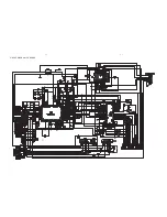
CIRCUIT DIAGRAM - CD BOARD

Summary of Contents for FWC185/77

Page 1: ...hotocopying or otherwise without the prior permission of Philips Handling chip components 1 1 Leadfree and safety information 1 2 Technical specification 2 1 Service tools 1 1 Service measurement setup 2 2 Connections and controls 3 1 3 3 Disassembly diagram 4 1 4 3 Wiring diagram 5 1 Display board circuit diagram 6 1 layout diagram 6 2 CD board circuit diagram 7 1 layout diagram 7 2 Main board ci...

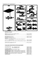
Page 2: ...1 1 HANDLING CHIP COMPONENTS ...

Page 3: ...1 2 ...

Page 4: ...Sensitivity at 26sb S N 4 4 mV M Selectivity at 18 kHz Bandwidth 22 dB IF rejection 45 dB Image rejection 28 dB Distortion 5 AMPLIFIER Output power 2 x 15 W RMS Speaker impedance 3 ohm Frequency response Within 3dB 60Hz 16 kHz Dynamic Bass Boost ON 8dB 3dB at 60Hz CASSETTE RECORDER Number of tracks 2 x 2 stereo Tape speed 4 76 cm sec 2 5 1 5 Wow and flutter 0 35 DIN Fast wind rewind time 130 sec W...

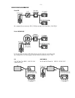
Page 5: ... 707 89001 Tuner AM MW LW To avoid atmospheric interference all AM measurements have to be carried out in a Faraday s cage Use a bandpass filter or at least a high pass filter with 250kHz to eliminate hum 50Hz 100Hz RF Generator e g PM5326 Ri 50 L R LEVEL METER e g Sennheiser UPM550 with FF filter S N and distortion meter e g Sound Technology ST1700B DUT CD RECORDER Use Audio Signal Disc SBC429 48...

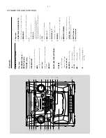
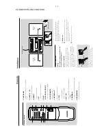
Page 6: ...back opens the tape holder Å interrupts playback or recording Tape deck FUNCTION TUNER TAPE CD selects CD tape or radio source of sound PROGRAM programs tracks and reviews the program n 3 5 mm headphone socket Helpful hints Adjust the volume to a moderate level before you plug in the headphones Connecting headphones will switch off the speakers ÉÅ starts or pauses CD playback DISC 1 2 3 selects a ...

Page 7: ...r cable into the socket then release the clip B FM antenna 1 Extend the wire antenna and move the antenna in different positions for optimal reception as far away as possible from the TV VCR or other radiation sources 2 Fix the antenna s end to the wall Rear connections Warning Never make or change connections with the power supply switched on Speakers connection Use the supplied speakers only Usi...

Page 8: ...ed black wire to Red Black Press the clip of the red terminal and fully insert the stripped portion of the coloured or marked speaker cable into the socket then AC power cord FM wire antenna Speaker right Speaker left 1 2 Red Black Using AC power Make sure all connections have been made before switching on the power supply Connect the power cable supplied to AC and to the wall socket This switches...

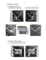
Page 9: ...move top rear cabinet A1 Remove screws T3x10 3pcs A2 Remove screws M3x12 4pcs A3 A4 A3 Remove screws M3x10 12pcs A4 Remove screws M3x16 2pcs C1 C2 C Remove left right side screws C1 Remove screws M3x12 M3x10 1pcs C1 Remove screws M3x12 M3x10 1pcs ...

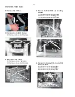
Page 10: ...8 1pcs E2 Remove screws M3x10 3pcs F2 F3 F1 F Remove the Main PCB and mounting bracket F1 Remove screws M3x12 3pcs F2 Remove screws M3x10 5pcs F3 Remove screws M3x10 6pcs G1 G2 G3 G Remove the Display PCB Volume PCB and metal plate G1 Remove screws M3x10 9pcs G2 Remove screws M3x10 3pcs G3 Remove screws M3x8 5pcs D1 D1 Remove the CD Door ...

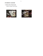
Page 11: ...DISASSEMBLY DIAGRAMS H Remove the Power board Remove screws T3x10 7pcs H H 4 3 ...

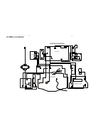
Page 12: ...CN703 CN701 CN702 CN704 AC1 AC2 KEY PCB WIRING DIAGRAM 5 1 5 1 ...

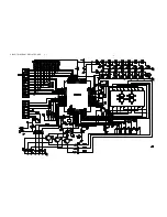
Page 13: ...6 1 CIRCUIT DIAGRAM DISPLAY BOARD 6 1 ...

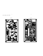
Page 14: ...6 2 6 2 LAYOUT DIAGRAM DISPLAY BOARD SIDE A SIDE B ...

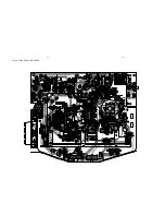
Page 15: ...7 1 7 1 CIRCUIT DIAGRAM CD BOARD ...

Page 16: ...7 2 LAYOUT DIAGRAM CD BOARD 7 2 ...

Page 17: ...8 1 8 1 CIRCUIT DIAGRAM MAIN BOARD ...

Page 18: ...8 2 8 2 LAYOUT DIAGRAM MAIN BOARD ...

Page 19: ...CIRCUIT DIAGRAM POWER BOARD LAYOUT DIAGRAM POWER BOARD 9 1 9 1 ...

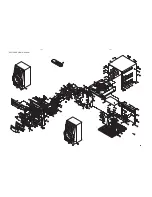
Page 20: ...10 1 10 1 EXPLODED VIEW DIAGRAM ...

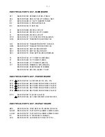
Page 21: ...ACKET 15 9940 000 04115 DIAL DRUM 16 9965 000 40344 PRO STOP REP KNOB SIL 433C 17 9965 000 40345 UP DN VOL KNOB 18 9965 000 40346 DISC SELECT KNOB SIL 433C 19 9965 000 40347 OPEN CLOSE KNOB 931070B 20 9965 000 40348 PLAY KNOB 3KEYSSIL 433C 21 9965 000 40349 FUNC KNOB 931070B 22 9965 000 40350 TUNING KNOB 931070B 23 9965 000 40351 BAND KNOB 931070B 24 9965 000 40352 POWER KNOB 032C 25 9965 000 4035...

Page 22: ...00 04148 I F T 10MM 740 ORANGE T3 9940 000 03649 I F T 10MM 910 RED T4 9940 000 03648 I F T 10MM 621 BLACK TC1 9940 000 00254 TRIMMER 10PF 6MM WH 9940 000 03645 FERRITE BAR D10X80MM 9940 000 04149 AM COIL AD M3 115 20T ELECTRICAL PARTS LIST POWER BOARD C710 9965 000 40361 E CAP 8200UF 25V 20 10 D701 9965 000 40362 RECTIFIER DIODE 1N5402 3A 200V D702 9965 000 40362 RECTIFIER DIODE 1N5402 3A 200V D7...

Page 23: ...000 40365 CRYSTAL 8MHZ HC 49 US 30PPM 9940 000 00265 LED LAMP MICRO 9940 000 04157 TACT SWITCH 6X6MM H 5MM 5LEGS ELECTRICAL PARTS LIST KEY BOARD POWER 9940 000 04157 TACT SWITCH 6X6MM H 5MM 5LEGS VOL DN 9940 000 04157 TACT SWITCH 6X6MM H 5MM 5LEGS VOL UP 9940 000 04157 TACT SWITCH 6X6MM H 5MM 5LEGS ELECTRICAL PARTS LIST JACK BOARD 9940 000 04165 SPEAKER JACK ELECTRICAL PARTS LIST HEADPHONE BOARD H...

Reviews: