3 - 2
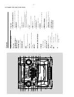
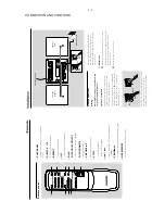
CONNECTION AND CONTROLS
Remote contr
ol
1
PO
WER ON
–
switches the system on or to standb
y
mode
2
DIGITS 0 - +10
–
CD:
selects a tr
ack n
umber
3
REPEA
T
– selects repeat modes
4
ÉÅ
–
star
ts or pauses CD pla
yback
5
DISC
DISC 1/DISC 2/DISC 3
–
selects a disc tr
ay f
or pla
yback
DISC CHANGE
–
changes disc tr
ay
s
6
V
OLUME
3
,
4
–
adjusts the v
olume level
7
ST
OP
–
stops CD pla
yback
–
er
ase a CD program
8
4
/
¢
–
skips or searches CD tr
acks backwards/
fo
rwards
9
PR
OGRAM
–
progr
ams tr
acks and reviews the progr
am
0
OPEN/CLOSE
–
press to open/closes the disc tr
ay
1
0
2
3
4
5
6
9
8
7
Press the clip of the b
lack ter
minal and full
y
inser
t the str
ipped por
tion of the black (or
unmar
ked) speak
er cab
le into the socket,
then
release the clip
.
B
FM antenna
1
Extend the wire antenna and mo
ve
the antenna
in different positions f
or optimal reception (as far
aw
ay
as possib
le from the
TV
, VCR or other
radiation sources).
2
Fix the antenna’
s end to the wall.
Rear connections
W
arning:
Ne
ver mak
e or change connections with
the po
wer supply s
witched on.
Speak
ers connection
Use the supplied speaker
s onl
y. Using other
speak
er
s can damage the set or the sound
quality will be negativ
el
y aff
ected.
Connect the speak
er wires to the SPEAKERS
terminals,
r
ight speak
er to
“
R
”
and left speaker to
“
L
”,
red (labelled red) wire to
“
+
”
and b
lack
(labelled b
lack) wire to
“
-
”.
Red
Blac
k
+
-
Press the clip of the red ter
minal and full
y inser
t
the str
ipped por
tion of the coloured (or
mar
ked) speak
er cab
le into the socket,
then
AC
po
w
er cor
d
FM wir
e antenna
Speak
er
(right)
Speak
er
(left)
1
2
Red
Blac
k
+
-
Summary of Contents for FWC185/77
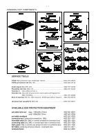
Page 2: ...1 1 HANDLING CHIP COMPONENTS ...
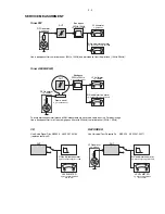
Page 3: ...1 2 ...
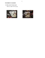
Page 11: ...DISASSEMBLY DIAGRAMS H Remove the Power board Remove screws T3x10 7pcs H H 4 3 ...
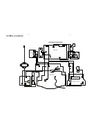
Page 12: ...CN703 CN701 CN702 CN704 AC1 AC2 KEY PCB WIRING DIAGRAM 5 1 5 1 ...
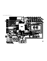
Page 13: ...6 1 CIRCUIT DIAGRAM DISPLAY BOARD 6 1 ...
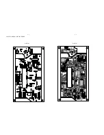
Page 14: ...6 2 6 2 LAYOUT DIAGRAM DISPLAY BOARD SIDE A SIDE B ...
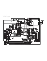
Page 15: ...7 1 7 1 CIRCUIT DIAGRAM CD BOARD ...
Page 16: ...7 2 LAYOUT DIAGRAM CD BOARD 7 2 ...
Page 17: ...8 1 8 1 CIRCUIT DIAGRAM MAIN BOARD ...
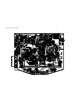
Page 18: ...8 2 8 2 LAYOUT DIAGRAM MAIN BOARD ...
Page 19: ...CIRCUIT DIAGRAM POWER BOARD LAYOUT DIAGRAM POWER BOARD 9 1 9 1 ...

