background image

10 - 3

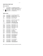
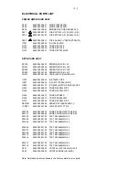
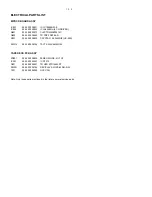
ELECTRICAL PARTS LIST

MP3/CD BOARD ASSY

IC801

9965 000 38871

IC LC78690NW-E

IC802

9965 000 38842

IC LA6548NH (4 CH DRIVER)

Q801

9940 000 03973

CHIP TR MMBT9015C

Q802

9965 000 38840

TR PNP 2SB764-D

X801

9965 000 38825

CRYSTAL 16.9344MHZ (HC-49S)

SW314

9940 000 04792

TACT SW 6X6MM H4.3

TAPE DECK PCB ASSY

ZD201

9965 000 38826

ZENER DIODE -5% 7V5

IC201

9940 000 04007

IC D7312

Q201

9965 000 38841

TR NPN STD1862LPF

SW201

9940 000 04784

REC/PLAY SW (PS-62D01-NS)

T201

9940 000 04008

OSC COIL

Note: Only these parts mentioned in the list are normal service parts.

Summary of Contents for FWM139

Page 1: ... Leadfree and safety information 1 2 Technical specification 2 1 Service measurement setup 2 2 Connections and controls 3 1 3 2 Disassembly diagram 4 1 4 2 Set block diagram 5 1 Set wiring diagram 5 2 Circuit Diagram part 1 Circuit diagram CPU Display board 6 1 Circuit diagram AMP Power board 6 2 Layout Diagram CPU Display AMP Power boards Top view 6 3 Bottom view 6 4 Circuit Diagram part 2 Circui...

Page 2: ...1 1 HANDLING CHIP COMPONENTS ...

Page 3: ...1 2 ...

Page 4: ...kHz Bandwidth 18 dB IF rejection 45 dB Image rejection 28 dB Distortion 5 AMPLIFIER Output power 2 x 20 W RMS Speaker impedance 8 ohm Frequency response Within r 3dB 63Hz 16 kHz Hyper bass sound ON 8dB r 3dB at 125Hz Digital sound control Rock Pop Jazz Classic Headphone output 32 mW r 2dB at 32 CASSETTE RECORDER Number of tracks 2 x 2 stereo Tape speed 4 76 cm sec 2 5 1 5 Wow and flutter 0 4 DIN F...

Page 5: ... 707 89001 Tuner AM MW LW To avoid atmospheric interference all AM measurements have to be carried out in a Faraday s cage Use a bandpass filter or at least a high pass filter with 250kHz to eliminate hum 50Hz 100Hz RF Generator e g PM5326 Ri 50 L R LEVEL METER e g Sennheiser UPM550 with FF filter S N and distortion meter e g Sound Technology ST1700B DUT CD RECORDER Use Audio Signal Disc SBC429 48...

Page 6: ...g 89 BE hideh 89 eaVnWVX dg ZgVhZh V 89 egd gVb IJC C ijcZh id V gVY d hiVi dc 9 HEA6N Y heaVn i Z XjggZci i bZ 977 9ncVb X 7Vhh 7ddhi Zc VcXZh i Z WVhh KDAJB VY_jhih i Z kdajbZ aZkZa 8 n XdccZXi ZVYe dcZh IVeZ 9ZX DeZgVi dc G 8DG9 hiVgih gZXdgY c EA6N hiVgih eaVnWVX G L à L9 á Vhi gZl cYh dglVgYh i Z iVeZ HIDE DE C hideh i Z iVeZ0 deZch i Z iVeZ XdbeVgibZci E6JH Å eVjhZh gZXdgY c dg eaVnWVX G E 6...

Page 7: ...g ZY l gZ id jaan chZgi i Z hig eeZY edgi dc d i Z heZV Zg l gZ cid i Z iZgb cVa Vh h dlc CdiZh dg dei bVa hdjcY eZg dgbVcXZ jhZ i Z hjeea ZY heZV Zgh 9d cdi XdccZXi bdgZ i Vc dcZ heZV Zg id Vcn dcZ eV g d heZV Zg iZgb cVah 9d cdi XdccZXi heZV Zgh l i Vc beZYVcXZ adlZg i Vc i Z heZV Zgh hjeea ZY EaZVhZ gZ Zg id i Z HE 8 86I DCH hZXi dc d i h bVcjVa HeZV Zg g i HeZV Zg aZ i NSERTING BATTERIES INTO ...

Page 8: ...SSEMBLY DIADRAMS A A Switch on the set Press OPEN CLOSE to open the CD Tray Remove CD Door B2 B3 B1 B Remove Top Cabinet B1 Remove screws SP 3x12 6 pcs B2 Remove screws SP 3x12 4 pcs B3 Remove screws SP 3x12 4 pcs ...

Page 9: ...ews SP 3x15 2 pcs C3 Remove screws SP 3x10 1 pcs D1 D Remove Bottom Cabinet Solder out the FM antenna wire D1 Remove screws SP 3x12 2 pcs E1 E Remove Main PCB Assy E1 Remove screws SP 3x10 Washer head 2 pcs F2 F1 F Remove Key Board Assembly F1 Remove screws SP 3x10 10 pcs F2 Remove screws SP 3x10 4 pcs ...

Page 10: ...5 1 5 1 SET BLOCK DIAGRAM ...

Page 11: ...5 2 5 2 SET WIRING DIAGRAM ...

Page 12: ...6 1 6 1 CIRCUIT DIAGRAM CPU DISPLAY BOARD ...

Page 13: ...6 2 6 2 CIRCUIT DIAGRAM AMP POWER BOARD ...

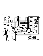
Page 14: ...6 3 6 3 LAYOUT DIAGRAM CPU DISPLAY AMP POWER BOARD TOP VIEW ...

Page 15: ...6 4 6 4 LAYOUT DIAGRAM LAYOUT DIAGRAM CPU DISPLAY AMP POWER BOARD BOTTOM VIEW ...

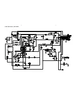
Page 16: ...7 1 7 1 CIRCUIT DIAGRAM CASSETTE PART ...

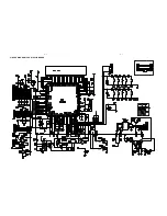
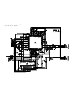
Page 17: ...7 2 7 2 CIRCUIT DIAGRAM CD MP3 PART ...

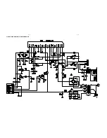
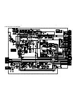
Page 18: ...7 3 7 3 CIRCUIT DIAGRAM TUNER AUDIO PART ...

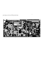
Page 19: ...8 1 LAYOUT DIAGRAM MAIN BOARD TOP VIEW 8 1 ...

Page 20: ...8 2 LAYOUT DIAGRAM MAIN BOARD TOP VIEW 8 2 ...

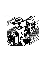
Page 21: ...9 1 9 1 EXPLODED VIEW DIAGRAM ...

Page 22: ...R SPRING 23 9965 000 38849 9965 000 38812 TUNING KNOB 24 9940 000 04694 9940 000 04694 FRONT CAB 25 9940 000 04724 9940 000 04724 TUNING KNOB GEAR 28 9940 000 04705 9940 000 04705 REC KNOB 29 9940 000 04704 9940 000 04704 PLAY KNOB 30 9940 000 04707 9940 000 04707 REW KNOB 31 9940 000 04706 9940 000 04706 F FWD KNOB 32 9940 000 04703 9940 000 04703 STOP KNOB 33 9940 000 04712 9940 000 04712 PAUSE ...

Page 23: ...D10XL60 PVC101 9940 000 04775 PVC DF443DF04 A04 ZD601 9940 000 04751 ZENER DIODE 5 9V1 ZD902 9965 000 38830 ZENER DIODE 5 12V ZD903 9940 000 04749 ZENER DIODE 5 6V8 ZD904 9965 000 38828 ZENER DIODE 5 3V9 IC101 9940 000 03962 IC TA2111NG IC601 9965 000 38832 IC LC75342 TLM E IC901 9965 000 38833 IC LM7805CZ Q104 9965 000 38858 TR NPN 9018G Q105 9965 000 38838 TR NPN 2SC5343YPF Q903 9965 000 38859 T...

Page 24: ... 000 04737 IC D6208 MOTOR DRIVER SOT8 Q303 9965 000 38838 TR NPN 2SC5343YPF Q305 9965 000 38838 TR NPN 2SC5343YPF Q306 9965 000 38837 TR NPN STD882 Q308 9965 000 38872 TR PNP SRA2202M Q313 9965 000 38838 TR NPN 2SC5343YPF REM301 9940 000 03956 SENSOR AT136B 36KHZ 5V LCD301 9940 000 04789 LCD SDT M3797 TP 4 SW300 9965 000 38829 SLIDE SW SSH 23D15 G5 NS SW301 9965 000 38829 SLIDE SW SSH 23D15 G5 NS ...

Page 25: ...0 38840 TR PNP 2SB764 D X801 9965 000 38825 CRYSTAL 16 9344MHZ HC 49S SW314 9940 000 04792 TACT SW 6X6MM H4 3 TAPE DECK PCB ASSY ZD201 9965 000 38826 ZENER DIODE 5 7V5 IC201 9940 000 04007 IC D7312 Q201 9965 000 38841 TR NPN STD1862LPF SW201 9940 000 04784 REC PLAY SW PS 62D01 NS T201 9940 000 04008 OSC COIL Note Only these parts mentioned in the list are normal service parts ...

Reviews: