2
-3
2
-3
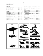
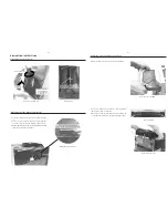
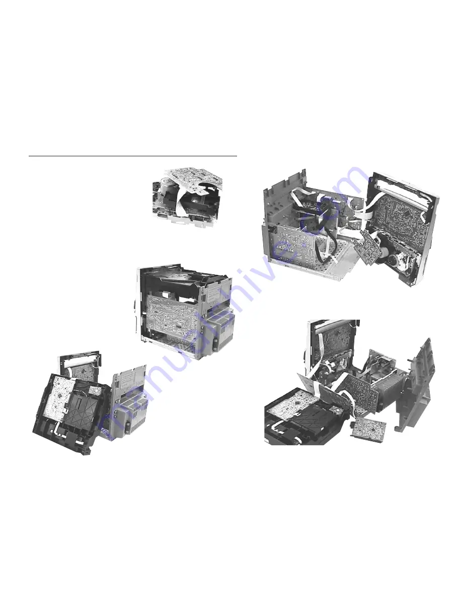
Service pos D
Service pos A
Service pos C
Repair Hints
3) During repair it is possible to disconnect the Tuner board
and CDC Module completely unless the fault is sus-
pected to be in that area. This will not affect the
performance of the rest of the set.
4) Due to the short flex cable wires in the ETF Module, the
pc board should be disconnected and reconnected on
the reverse side of the tape mechanism to keep it
electrically connected during repair. See picture 3.
Note: The flex cables are very fragile, care should be taken
not to damage them during repair. After repair, be
very sure that the flex cables are inserted properly
into the flex sockets before encasing, otherwise faults
may occurs.
Picture 3
Service pos B
Summary of Contents for FWM15/21
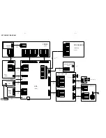
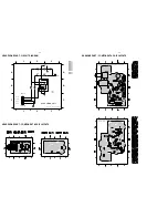
Page 52: ...10 4 Wiring Disc Motor Inner switch Slide Motor Service Position ...
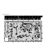
Page 69: ...11 6 POWER BOARD COPPERSIDE VIEW P2001 30 70W AN17850 PWR313 11 6 ...
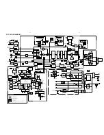
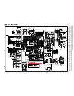
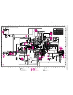
Page 75: ...12 4 12 4 SOURCE SELECTION SOUND PROCESSING CIRCUIT ...
Page 76: ...12 5 12 5 HEADPHONE AMPLIFIER I2 C EXPANDER CIRCUIT 1K ...

