10-3
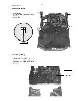
Pos 49 Guiding
Pos 48 Cam
Detail A
Dismantling of Tray
Service hints
1. Open the tray.
2. Release 2x catch as shown in fig. 2 and
Detail A
3. Pull tray out.
fig.2
Assembling of Tray
1. Turn Cam (pos. 48) clockwise to end
position.
2. If necessary - move Guiding (pos. 49) to the
right end position.
3. Insert the Tray.
Summary of Contents for FWM15/21
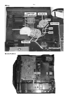
Page 52: ...10 4 Wiring Disc Motor Inner switch Slide Motor Service Position ...
Page 69: ...11 6 POWER BOARD COPPERSIDE VIEW P2001 30 70W AN17850 PWR313 11 6 ...
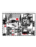
Page 75: ...12 4 12 4 SOURCE SELECTION SOUND PROCESSING CIRCUIT ...
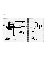
Page 76: ...12 5 12 5 HEADPHONE AMPLIFIER I2 C EXPANDER CIRCUIT 1K ...


