
3-1
3-1
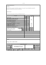
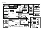
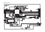
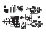
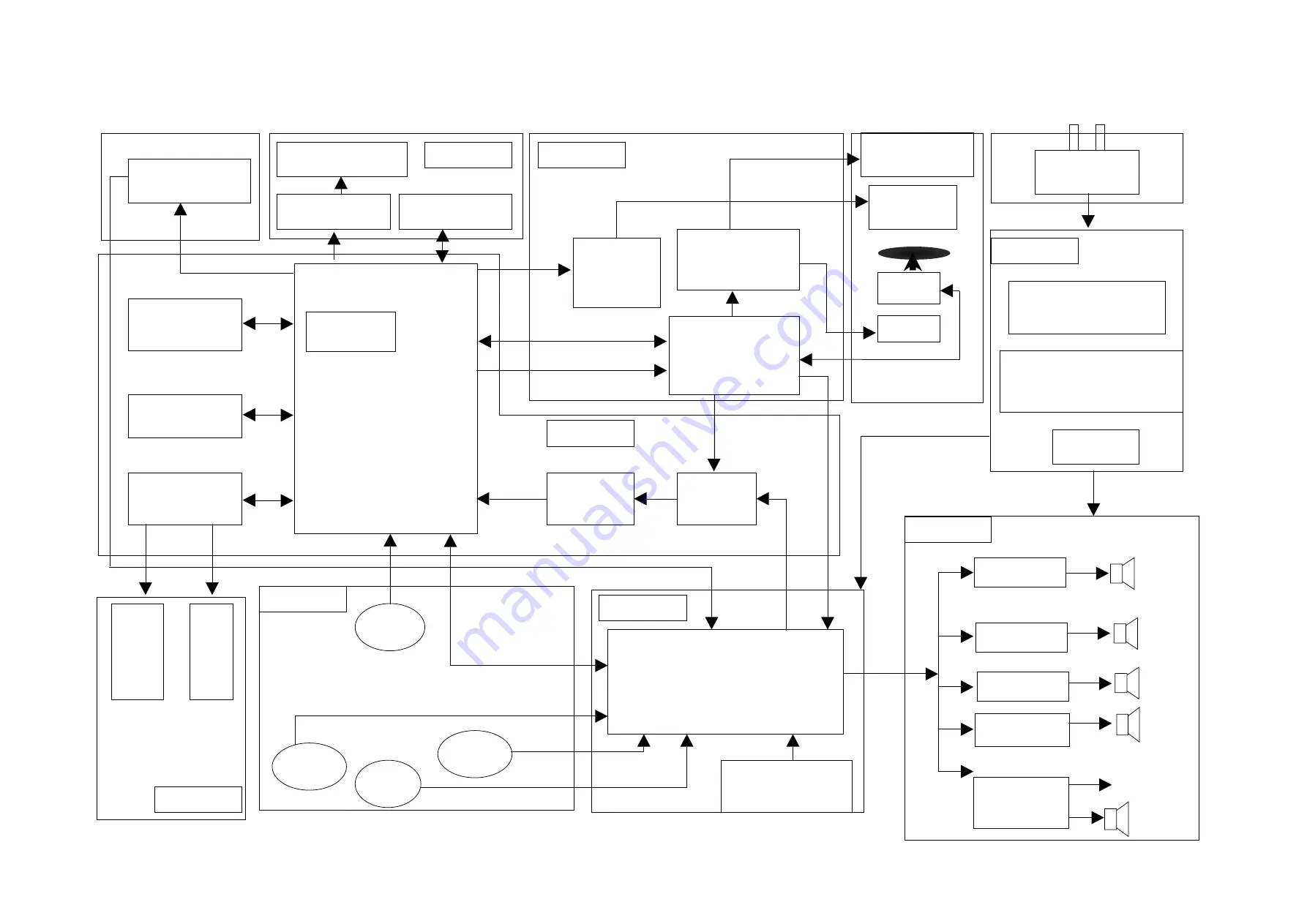
BLOCK DIAGRAM
CD SERVO
BU9543
RL
RR
MLC3895
144pin QFP
INPUT
VFD DRIVER
PT6311
MAIN L/R
INPUT
RC
SENSOR
16M SDRAM
8M SERIAL
8M SERIAL
FALSH
FALSH
SST29VF080B
SST29VF080B
PICK UP
MOTOR
ADC
WM8782
CD DOOR
DRIVER IC
TA7291S
MUX
74LVC157
AUX/PC
TUNER
(SI4730/31 )
MIC1/MIC2
USB1
REC
MOTOR DRIVER
AM5888S
IIC
MUL-L
/R
IIC
PCM
BCK,LRCK
,DATE
PCM
CD L
/R
TUNER L/R
CONTROL DATA
CD PCM
BCK,LRCK,
DATE
TDA8954*1
(SE)
FUNCTION IC
TDA7468D
3CD LOADER
TDA8954*1
(BTL)
SUB/R
2*150W
1*300W
USB2
PL
A
Y
LED DRIVER
BU2090F
IIC
MP3 LINE
USB CHANGE
FFE1.1S
CD DOOR MOTOR
SWITCH POWER SUPPLY
DC+/-39V
Main Supply Voltage
support Dock
DCK3060
AC CORD
CD Board
MCU Board
MIC Board
USB Board
AMP Board
MAIN Board
POWER Board
VFD Display
VFD Board
FWM998/ FWM9000
For 1000W
TDA8954*1
TDA8954*1
TDA8954*1
(BTL)
SUB/L
MAIN R
MAIN L
(BTL)
(BTL)
BT MODULE
Summary of Contents for FWT9200 Series
Page 22: ...WIRING DIAGRAM 4 1 4 1 ...
Page 24: ......
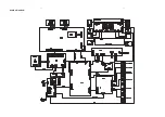
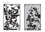
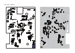
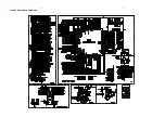
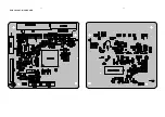
Page 25: ...6 2 6 2 PCB LAYOUT MAIN BOARD ...
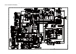
Page 26: ...7 1 7 1 CIRCUIT DIAGRAM DISPLAY BOARD ...
Page 27: ...PCB LAYOUT DISPLAY BOARD 7 2 7 2 ...
Page 29: ...8 2 8 2 PCB LAYOUT CD BOARD ...
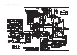
Page 30: ...CIRCUIT DIAGRAM MCU BOARD 9 1 9 1 ...
Page 31: ...PCB LAYOUT MCU BOARD 9 2 9 2 ...
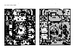
Page 34: ...PCB LAYOUT AMP BOARD 10 3 10 3 ...
Page 35: ...CIRCUIT DIAGRAM TUNER BOARD 11 1 11 1 ...
Page 36: ...PCB LAYOUT TUNER BOARD 11 2 11 2 ...
Page 37: ...12 1 12 1 EXPLODED VIEW ...


