4 - 1
4 - 1
A
B
1
2
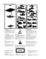
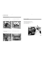
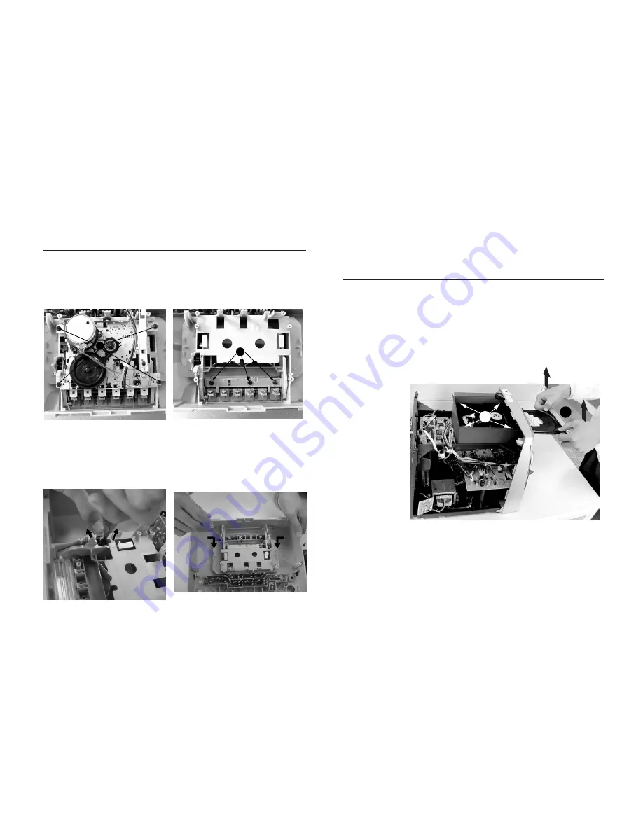
Dismantling of the Cassette Cover
1) Loosen 4 screws to remove the Cover Top of the set.
1) Loosen 4 screws to remove the Cassette Deck.
2) Loosen 4 screws to remove the Cassette Keys .
2) Loosen 2 screws to remove the Panel Left and 2 screws
to remove the Panel Right of the set.
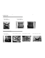
Connect AC power cord first, open the CD tray and remove
VCD Door as shown in the diagram below.
3)
4) Remove screws M3x10 - 4pcs.
Remove the Cassette Cover as indicated.
Dismantling of the VCD Module
3) Push the catch outside and take out damper gear
assembly as indicated.
.
4)
D
E
DISASSEMBLY DIAGRAM
Summary of Contents for FWV182
Page 2: ...1 1 HANDLING CHIP COMPONENTS ...
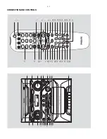
Page 6: ...3 1 3 6 ª 6 5 º 9 8 7 1 fi fl CONNECTION AND CONTROLS 1 4 7 3 0 8 9 6 5 2 fl ...
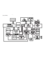
Page 12: ...5 1 5 1 SET BLOCK DIAGRAM ...
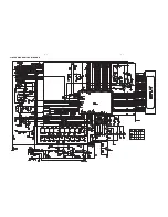
Page 13: ...5 2 5 2 SET WIRING DIAGRAM ...
Page 14: ...6 1 6 1 CIRCUIT DIAGRAM FRONT BOARD ...
Page 15: ...6 2 6 2 CIRCUIT DIAGRAM FRONT BOARD ...
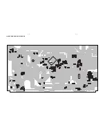
Page 16: ...6 3 6 3 LAYOUT DIAGRAM FRONT BOARD ...
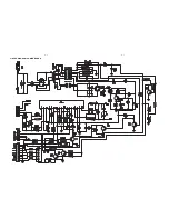
Page 17: ...7 1 7 1 CIRCUIT DIAGRAM VCD BOARD ...
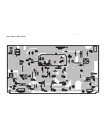
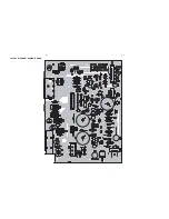
Page 18: ...7 2 7 2 LAYOUT DIAGRAM VCD BOARD ...
Page 19: ...8 1 8 1 CIRCUIT DIAGRAM POWER BOARD ...
Page 20: ...8 2 8 2 LAYOUT DIAGRAM POWER BOARD ...
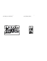
Page 21: ...9 1 9 1 LAYOUT DIAGRAM ANT BOARD LAYOUT DIAGRAM VOL SELECT BOARD ...
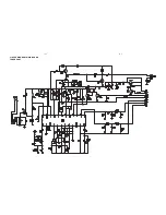
Page 22: ...10 1 10 1 CIRCUIT DIAGRAM MAIN BOARD TUNER PART ...
Page 23: ...10 2 10 2 CIRCUIT DIAGRAM MAIN BOARD TAPE PART ...
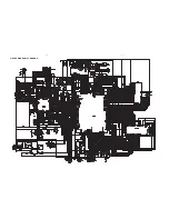
Page 24: ...10 3 10 3 CIRCUIT DIAGRAM MAIN BOARD ...
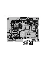
Page 25: ...10 4 10 4 LAYOUT DIAGRAM MAIN BOARD ...
Page 26: ...10 5 10 5 LAYOUT DIAGRAM MAIN BOARD ...


