background image

3 - 3

Pr

eparations

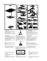
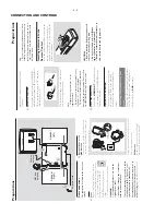
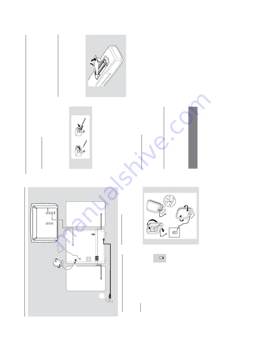
Rear connections

The type plate is located at the r

ear of the

system.

A

Po

w

e

r

Bef

ore connecting the 

A

C

 po

w

er cord to the

wall outlet,

 ensure that the f

ollo

wing are done;

If y

our system is equipped with a

V

oltage Selector

, set the 

V

O

LT

A

G

E

SELECT

OR to the local po

w

er line

voltage

.

All other connections ha

ve

 been made

.

WARNING!

–F

or optimal performance

, use only the

original po

wer cable

.

–N

ev

er mak

e or change an

y connections

with the po

wer s

w

itched on.

To

 av

oid o

verheating of the system,

 a safety

circuit has been built in.

  Ther

efor

e

, your

system may s

witch to Standb

y mode

automatically under e

xtr

eme conditions

.  If

this happens

, let the system cool do

wn

befor

e r

eusing it 

(not availab

le f

or all ver

sions)

.

VOLTAGE

SELECTOR

110V-

127V

220V-

240V

B

Antennas Connection

MW Antenna

Connect the supplied MW loop antenna to the

“AM antenna”

 ter

minal.

 Adjust the position of

the antenna f

or optimal reception.


Fix the claw 

to the slot

MW ANTENNA


P

osition the antenna as far as possib

le from a 

TV

,

VCR or other r

adiation source

.

FM Antenna

It is unnecessar

y to connect the FM pigtail

antenna since it is f

ix

ed to the main unit.

VOLTAGE

SELECTOR

110V-

127V

220V-

240V

Speak

er

(r

ight)

Speak

er

(left)

MW loop 

antenna

AC

 po

w

er cord

FM wire 

antenna

  AM  ANTENNA

FM  ANTENNA

AUX/CDR

R     L

SPEAKERS 6

!&

R

+

Ö

L

LINE    OUT

VIDEO   OUT

IN

Television

L

R

IN

C

r

Cb

Y

A

B

C

D

12

3

Pr

eparations


Adjust the FM antenna f

or optimal FM stereo

reception.

C

Speak

ers Connection

Connect the speak

er wires to the SPEAKERS

terminals,

 r

ight speak

er to "

R

" and left speaker to

"

L

", colored (mar

ked) wire to "

+

" and b

lack

(unmar

ked) wire to "

-

".


Full

y inser

t the str

ipped por

tion of the speak

er

wire into the terminal as sho

wn.

Notes:

–F

or optimal sound perf

ormance

, use the

supplied speak

ers

.

Do not connect mor

e than one speak

er to any

one pair of 

+

/

-

 speak

er terminals.

Do not connect speak

er

s with an impedance

lo

wer than the speak

er

s supplied.

  Please ref

er to

the SPECIFIC

ATIONS section of this manual.

D

  Video Out Connection

Connect the 

VIDEO OUT 

 ter

minal at the rear

of the system to the 

TV or 

VCR 

VIDEO IN f

o

r

viewing or recording.

Optional connection

The optional equipment and connecting cords

are not supplied.

  Ref

er to the oper

ating

instr

uctions of the connected equipment f

o

r

details.

Connecting other equipment to your

system

Connect the audio left and right OUT ter

minals

of a 

TV

, VCR,

 Laser Disc pla

ye

r, D

VD pla

yer or

CD Recorder to the 

A

UX 

ter

minals.

Note:

If you ar

e connecting equipment with a mono

output (a single audio out terminal), connect it to

the 

A

UX left terminal.

  Alternatively

, you can use a

“single to double”

 cinc

h cable (the output sound

still r

emain mono).

Inser

ting batteries into the

Remote Contr

ol

Inser

t tw

o batter

ies (type R06 or 

AA) into the

remote control with the cor

rect polar

ity as

indicated b

y the 

+

 and 

-

 symbols inside the

batter

y compar

tment.

CA

UTION!

Remo

ve

 batteries if the

y are e

xhausted

or not to be used for a long time

.

Do not use old and new or different

types of batteries in combination.

Batteries contain chemical substances

, so

the

y should be disposed off pr

operly

.

or

CONNECTION AND CONTROLS

Summary of Contents for FWV182

Page 1: ...UCT Handling chip components 1 1 Information about lead free soldering 1 2 Technical specification 2 1 Service tools 2 1 Service measurement setup 2 2 Connections and controls 3 1 3 3 Maintenance and troubleshooting 3 4 Disassembly diagram 4 1 4 2 Set block diagram 5 1 Set wiring diagram 5 2 FRONT BOARD circuit diagram 6 1 layout diagram 6 2 6 3 VCD BOARD circuit diagram 7 1 layout diagram 7 2 POW...

Page 2: ...1 1 HANDLING CHIP COMPONENTS ...

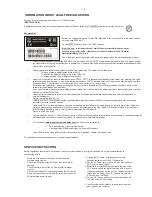
Page 3: ...ies has to be purchased at external companies Special information for BGA ICs always use the 12nc recognizable soldering temperature profile of the specific BGA for de soldering always use the lead free temperature profile in case of doubt lead free BGA ICs will be delivered in so called dry packaging sealed pack including a silica gel pack to protect the IC against moisture After opening dependen...

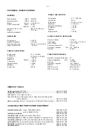
Page 4: ...125 8000 Hz S N ratio 45 dBA VIDEO PERFORMANCE Number of progarmmable track 20 Channel sepatation 1 kHz 50 dB S N ratio 62 dBA Frequency response 125 16000Hz MPEG1 VCD version 2 0 MPEG1 Layer 3 MPEG AUDIO MP3 CD bit rate 32 256 kbps SERVICE TOOLS Audio signal disc SBC 429 4822 397 30184 Playability test disc SBC 444 4822 397 30245 Test disc 5 disc without errors Test disc 5A disc with dropout erro...

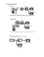
Page 5: ...Ω Aerial replacement Capacitor R 50Ω Bandpass 250Hz 15kHz e g 7122 707 48001 LF Voltmeter e g PM2534 DUT S N and distortion meter e g Sound Technology ST1700B Frame aerial e g 7122 707 89001 Tuner AM MW LW To avoid atmospheric interference all AM measurements have to be carried out in a Faraday s cage RF Generator e g PM5326 Ri 50Ω Low pass filter 22kHz L R LEVEL METER e g Sennheiser UPM550 with F...

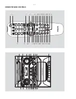
Page 6: ...3 1 3 6 ª 6 5 º 9 8 7 1 fi fl CONNECTION AND CONTROLS 1 4 7 3 0 8 9 6 5 2 fl ...

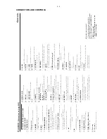
Page 7: ...ms disc tracks 6 ALBUM 1 1 ALBUM 3 4 for MP3 CD selects previous next album for Clock Timer adjusts the hours for VCD CD MP3 CD on the set only fast reverses forwards the disc 7 TITLE 4 for VCD CD MP3 CD selects a desired track preset for Clock Timer adjusts the minutes for VCD CD MP3 CD on the remote only fast reverses forwards the disc 8 for VCD CD MP3 CD starts or interrupts playback 9 9 for VC...

Page 8: ...onnection Connect the speaker wires to the SPEAKERS terminals right speaker to R and left speaker to L colored marked wire to and black unmarked wire to Fully insert the stripped portion of the speaker wire into the terminal as shown Notes For optimal sound performance use the supplied speakers Do not connect more than one speaker to any one pair of speaker terminals Do not connect speakers with a...

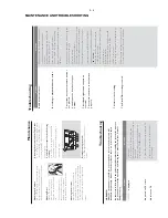
Page 9: ...onia or abrasives Cleaning Discs When a disc becomes dirty clean it with a cleaning cloth Wipe the disc from the centre out Do not use solvents such as benzene thinner commercially available cleaners or antistatic spray intended for analogue records Cleaning the disc lens After prolonged use dirt or dust may accumulate at the disc lens To ensure good playback quality clean the disc lens with Phili...

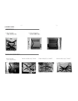
Page 10: ...e Keys 2 Loosen 2 screws to remove the Panel Left and 2 screws to remove the Panel Right of the set Connect AC power cord first open the CD tray and remove VCD Door as shown in the diagram below 3 4 Remove screws M3x10 4pcs Remove the Cassette Cover as indicated Dismantling of the VCD Module 3 Push the catch outside and take out damper gear assembly as indicated 4 D E DISASSEMBLY DIAGRAM ...

Page 11: ... screws M3x10 2pcs F Remove screws M3x10 13pcs Front Board D Remove screws M3x10 12pcs VCD Board E Remove screws M3x10 3pcs Main Board B Remove Left and Right panel B1 Remove screws M3x10 2pcs B2 Remove screws M3x10 2pcs B1 B2 Dismantling of Rear Portion Dismantling of the Front Cabinet and PCB Boards E F D DISASSEMBLY DIAGRAM ...

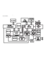
Page 12: ...5 1 5 1 SET BLOCK DIAGRAM ...

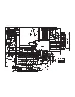
Page 13: ...5 2 5 2 SET WIRING DIAGRAM ...

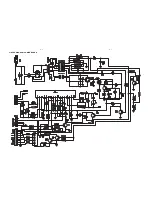
Page 14: ...6 1 6 1 CIRCUIT DIAGRAM FRONT BOARD ...

Page 15: ...6 2 6 2 CIRCUIT DIAGRAM FRONT BOARD ...

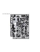
Page 16: ...6 3 6 3 LAYOUT DIAGRAM FRONT BOARD ...

Page 17: ...7 1 7 1 CIRCUIT DIAGRAM VCD BOARD ...

Page 18: ...7 2 7 2 LAYOUT DIAGRAM VCD BOARD ...

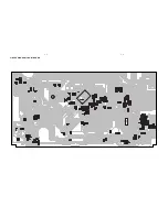
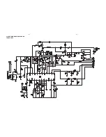
Page 19: ...8 1 8 1 CIRCUIT DIAGRAM POWER BOARD ...

Page 20: ...8 2 8 2 LAYOUT DIAGRAM POWER BOARD ...

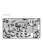
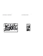
Page 21: ...9 1 9 1 LAYOUT DIAGRAM ANT BOARD LAYOUT DIAGRAM VOL SELECT BOARD ...

Page 22: ...10 1 10 1 CIRCUIT DIAGRAM MAIN BOARD TUNER PART ...

Page 23: ...10 2 10 2 CIRCUIT DIAGRAM MAIN BOARD TAPE PART ...

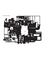
Page 24: ...10 3 10 3 CIRCUIT DIAGRAM MAIN BOARD ...

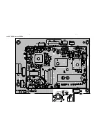
Page 25: ...10 4 10 4 LAYOUT DIAGRAM MAIN BOARD ...

Page 26: ...10 5 10 5 LAYOUT DIAGRAM MAIN BOARD ...

Page 27: ...11 1 11 1 EXPLODED VIEW DIAGRAM ...

Page 28: ...38 3CDC DOOR 21 994000004591 RING POWER 22 994000004579 POWER BUTTON 23 994000004589 POWER BUTTON BASE 24 994000004642 DSC BUTTON 25 994000004644 TUNING KNOB 26 994000004575 PROGRAM KEYS 27 994000004643 CONTROL KEYS 29 994000004581 DBB BUTTON 34 994000004563 PANEL LEFT 35 994000004564 PANEL RIGHT 36 994000004567 CHASSIS PLASTIC 37 994000004572 TOP COVER 38 994000004628 VCD MECHA CASING ASS Y 48 99...

Page 29: ...C KA7812 IC202 994000001201 IC NJM4556AM IC203 994000001201 IC NJM4556AM IC205 994000004533 IC YD7312 IC201 994000004607 IC PT2314 IC206 994000004608 IC TA2111F CF202 994000004609 CER FILTER SFU455B CF201 994000003642 CER FILTER LT10 7MA5 A T202 994000004537 FILTER JT10 7MG82 A L203 994000004538 I F T 10148BK7 L215 994000004611 I F T 7mm 7M1A2224N T203 994000004612 AM I F T AH07 835444NP SW201 994...

Page 30: ...A GBU8D IC101 994000001203 IC TDA8947J N3 CON104 994000004547 SPK JACK MSP 134V 05 LF J201 994000004617 RCA JACK 4P F103 994000001349 FUSE RADIAL T1 6A 250V F102 994000001223 FUSE RADIAL T5A 250V IC TRANSISTORS ELECTRICAL PARTSLIST AMP BOARD Note Only these parts mentioned in the list are normal service parts MISCELLANEOUS ...

Page 31: ...VOLUME VR400 994000001241 ROTARY ENCODER XT402 994000004615 CRYSTAL 32 768KHZ 12 5PF XT401 994000004616 CRYSTAL 4 500MHz SW401 994000001243 TACT SWITCH SW402 994000001243 TACT SWITCH SW403 994000001243 TACT SWITCH SW404 994000001243 TACT SWITCH SW409 994000001243 TACT SWITCH SW410 994000001243 TACT SWITCH SW411 994000001243 TACT SWITCH SW412 994000001243 TACT SWITCH SW413 994000001243 TACT SWITCH ...

Page 32: ...RAM HY57V161610ETP 7 U2 994000004622 IC LA6548NH U1 994000004623 IC LC78637E U6 994000004624 IC SPCA711A PLCC32 U3 994000004625 IC SPCA718A 128 XT2 994000004626 CRYSTAL 27 000MHZ 2PIN JK1 994000004627 RCA JACK 1P 994000005008 VCD BOARD ASSY IC TRANSISTORS ELECTRICAL PARTSLIST VCD BOARD MISCELLANEOUS Note Only these parts mentioned in the list are normal service parts ...

Page 33: ...1 SWITCH SDKPA40300 F101 FUSE RADIAL LT 2A 250V 994000001225 994000001226 994000001323 994000001222 MISCELLANEOUS ELECTRICAL PARTSLIST VOL SELECT BOARD Note Only these parts mentioned in the list are normal service parts ...

Page 34: ...4000004632 10P FFC CABLE L 80mm 994000004633 13P FFC CABLE L 80mm 994000004631 TRANSFORMER EI66 127 240V 994000001329 AC CORD VDE APP 1 83M Note Only these parts mentioned in the list are normal service parts MISCELLANEOUS ELECTRICAL PARTSLIST ...

Reviews: