

3 - 4
Radio r
eception is poor
.
Recor
ding or pla
yback cannot be made
.
The system does not r
eact when buttons
ar
e pr
essed.
Sound cannot be hear
d or is of poor
quality
.
The left and right sound outputs ar
e
re
v
ersed.
The r
emote contr
ol does not function
pr
operl
y.
The timer is not w
orking.
The Clock/Timer setting is erased.
If the signal is too w
eak,
adjust the antenna or
connect an exter
nal antenna for better
reception.
Increase the distance betw
een the Mini HiFi
System and y
our
TV or
VCR.
Clean deck par
ts,
see
“Maintenance”.
Use onl
y nor
mal (IEC I) tape f
or recording.
Appl
y a piece of adhesiv
e tape o
ver the missing
tab space
.
Remo
ve
and reconnect the
A
C
po
w
er plug and
switch on the system again.
Adjust the v
olume
.
Disconnect the headphones.
Check that the speaker
s are connected cor
rectl
y.
Check if the str
ipped speak
er wire is clamped.
Check the speaker connections and location.
Select the source (VCD/CD or
TUNER,
f
o
r
example) bef
ore pressing the function b
utton
(,
4
,
¢
).
Reduce the distance betw
een the remote
control and the system.
Inser
t the batter
y with its polar
ities (+/– signs)
aligned as indicated.
Replace the batter
y.
P
oint the remote control directl
y to
ward IR
sensor on the front of the system.
Set the clock cor
rectl
y.
If a recording is in progress, stop the recording.
Po
w
er has been inter
rupted or the po
w
er cord
has been disconnected.
Reset the clock/timer
.
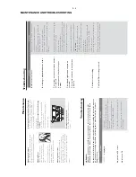
Pr
ob
lem
Solution
Tr
oub
leshooting
2;
Maintenance
Cleaning the Cabinet
Use a soft cloth slightl
y moistened with a mild
detergent solution.
Do not use a solution
containing alcohol,
spir
its,
ammonia or abr
asiv
es.
Cleaning Discs
When a disc becomes dir
ty
,
clean it with a cleaning cloth.
Wipe the disc from the centre
out.
Do not use solv
ents such as
benz
ene
, thinner
, commerciall
y
availab
le cleaner
s,
or antistatic
spra
y intended f
or analogue records.
Cleaning the disc lens
After prolonged use
, dir
t or dust may
accum
ulate at the disc lens.
T
o
ensure good
pla
yback quality
, clean the disc lens with Philips
CD Lens Cleaner or an
y commerciall
y a
vailab
le
cleaner
. Follo
w the instr
uctions supplied with
cleaner
.
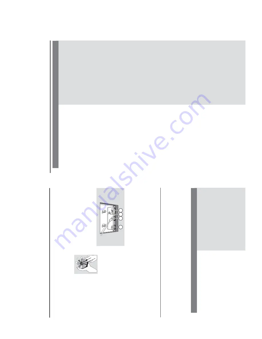
Cleaning the Heads and the
T
a
pe P
aths
To
ensure good recording and pla
yback quality
,
clean the heads
A
, the capstan(s)
B
, and
pressure roller(s)
C
after ev
er
y 50 hour
s of
tape oper
ation.
Caution:
Do not r
otate the heads during
cleaning.
Use a cotton swab slightl
y moistened with
cleaning fluid or alcohol.
You can also clean the heads b
y pla
ying a
cleaning tape once
.
A
A
B
C
Dema
gnetising the heads
Use a demagnetising tape a
vailab
le at y
our
dealer
.
W
ARNING
Under no cir
cumstances should y
ou tr
y to r
epair the system yourself,
as this will
in
validate the war
ranty
. Do not open the system as ther
e is a risk of electric shock.
If a fault occurs,
first check the points listed belo
w bef
or
e taking the system f
or r
epair
. If
y
ou ar
e unab
le to r
e
medy a pr
ob
lem b
y
f
ollo
wing these hints,
consult y
our dealer or
Philips f
or help
.
“
NO DISC
” is displa
y
ed.
No pictur
e on
TV screen.
No colour on
TV
.
Inser
t a disc
.
Check if the disc is inser
ted upside down.
W
ait until the moisture condensation at the lens
has cleared.
Replace or clean the disc
, see
“Maintenance”.
Use a f
inalised CD-R
W or CD-R.
Connect the cab
le betw
en the system and
TV
.
Change the system to the respectiv
e P
AL or
NTSC setting.
Pr
ob
lem
Solution
Tr
oub
leshooting
MAINTENANCE AND TROUBLESHOOTING
Summary of Contents for FWV182
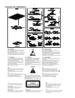
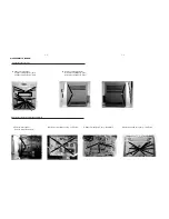
Page 2: ...1 1 HANDLING CHIP COMPONENTS ...
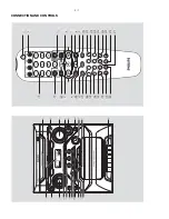
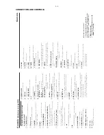
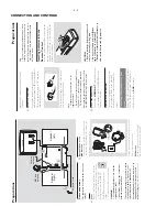
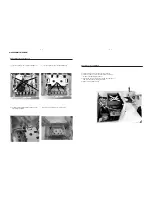
Page 6: ...3 1 3 6 ª 6 5 º 9 8 7 1 fi fl CONNECTION AND CONTROLS 1 4 7 3 0 8 9 6 5 2 fl ...
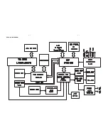
Page 12: ...5 1 5 1 SET BLOCK DIAGRAM ...
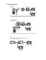
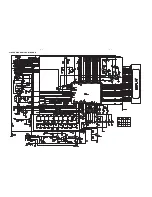
Page 13: ...5 2 5 2 SET WIRING DIAGRAM ...
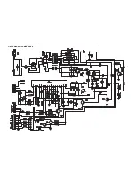
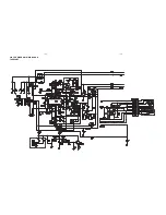
Page 14: ...6 1 6 1 CIRCUIT DIAGRAM FRONT BOARD ...
Page 15: ...6 2 6 2 CIRCUIT DIAGRAM FRONT BOARD ...
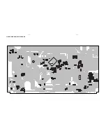
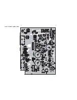
Page 16: ...6 3 6 3 LAYOUT DIAGRAM FRONT BOARD ...
Page 17: ...7 1 7 1 CIRCUIT DIAGRAM VCD BOARD ...
Page 18: ...7 2 7 2 LAYOUT DIAGRAM VCD BOARD ...
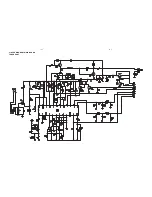
Page 19: ...8 1 8 1 CIRCUIT DIAGRAM POWER BOARD ...
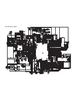
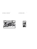
Page 20: ...8 2 8 2 LAYOUT DIAGRAM POWER BOARD ...
Page 21: ...9 1 9 1 LAYOUT DIAGRAM ANT BOARD LAYOUT DIAGRAM VOL SELECT BOARD ...
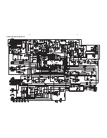
Page 22: ...10 1 10 1 CIRCUIT DIAGRAM MAIN BOARD TUNER PART ...
Page 23: ...10 2 10 2 CIRCUIT DIAGRAM MAIN BOARD TAPE PART ...
Page 24: ...10 3 10 3 CIRCUIT DIAGRAM MAIN BOARD ...
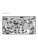
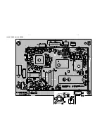
Page 25: ...10 4 10 4 LAYOUT DIAGRAM MAIN BOARD ...
Page 26: ...10 5 10 5 LAYOUT DIAGRAM MAIN BOARD ...


