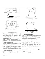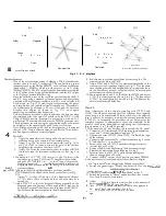
OVERALL RESPONSE AT CHROMINANCE DETECTOR
5 0 3 9 0 4 e
Fig. 14
M
—
DECODER ALIGNMENT
The three basic operations which have to be carried out are firstly
the adjustment of the A.P.C. loop to give a reference oscillator
output in the correct phase, secondly the setting up of the PAL
delay line and matrix circuits to give independent R-Y and B-Y
signal outputs, and lastly the alignment of the demodulator coil
assembly so that demodulation takes place on the correct axis
relative to the burst signal.
Alignment of the A.P.C. loop
Note.
The core of L7513 and certain other cores may require a
special star-shaped trimming tool (available as part of the Philips
trimming tool kit 800/TX, Cat. No. ECO2338). Any attempt to
adjust these cores with a non-standard tool may result in damage.
1.
L7651/2 (reference oscillator)
Connect a high impedance voltmeter between R7282/C7109 and
chassis. Short-circuit pin 2 of V7008 to chassis, and with no signal
input applied to the aerial socket, adjust L7651/2 for maximum
reading on the meter (approx. 170v).
2.
L7638 (reactance)
Apply a colour signal to the aerial socket and set up the controls
for a normal picture. Connect the slider of R7618 and also the
junction X7326/R7196 to chassis. Adjust L7638 to obtain stationary
colours on picture. Remove the connections from R7618, X7326/
R7196.
3.
L7624-6 (burst amplifier)
Apply a colour signal to the aerial socket and set up the controls
for a normal picture. Connect a high impedance voltmeter from
pin 2 of V7003 to chassis (+ ve lead to chassis). Adjust L7624-6
for maximum negative reading on the meter (approx.
–
4v.).
OVERALL CHROMINANCE BANDPASS
RESPONSE
5 0 3 9 0 4 e
Fig. 13
37MHz
33.5MHz
RESPON SE AT COLLECTOR T2143
5 0 3 9 0 4 f
Fig. 15
4.
R7618 (discriminator balance)
Apply a colour signal to the aerial socket and set up the controls
for a normal picture. Connect a high impedance voltmeter from
R7275/C7102 to chassis. Short-circuit pin 8 of V7003 to chassis.
Adjust R7618 (inside discriminator coil can) to give zero output
on the meter. Remove the short-circuit from pin 8 of V7003, then
slightly readjust L7638 for zero output on the meter.
Note.
If more than a slight readjustment is needed, re-check
operations 1 and 2.
5.
L7634 (indent. pulse amplifier)
Apply a colour signal to the aerial socket and set up the controls
for a normal picture. Connect an oscilloscope (adjusted to
display a 7.8kHz indent. pulse) to the collector of T7015, then
adjust L7634 for maximum output. This adjustment may also be
carried out using a high impedance voltmeter and a diode.
Proceed as follows: Connect the anode of the diode (0A70 or
similar) to the collector of T7015 and connect the meter between
the cathode of the diode and chassis (negative lead to chassis).
Adjust L7634 for maximum reading (about 15v.).
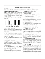
0 to -5v
-5v to -10v
RI
R2
R3
-120v Line
5K
5K
100K
(C10361
Preset
Preset
Chassis
earth
S D 3 9 3 2
Fig.
16. Bias network
37MHz
3507 MHz
<6dB
34-38dB
>4
0
d8 7-9 dB
-4-395MHz
T
i
41•5 MHz OVERALL LUMINANCE
>45dB
3 3 . N 5 M H z
31.5 MHz
1. F. RESPONSE
5o39o4a
Fig. 12
7
39.5MHz
35MHz
>20dB
Page Fourteen
Summary of Contents for G22K511
Page 3: ...G22K511 G25K512 Page Two ...
Page 12: ...Page Ten ...
Page 14: ...Page Eleven ...
Page 19: ...Page Fifteen ...


