F — MAINTENANCE NOTES
1.
Removal of backplate
Remove two screws from the top of the backplate which may
then be hinged out from the bottom and lifted away.
2.
Access to the convergence panel
The convergence panel is located on the front of the receiver in the
top right-hand corner, behind the upper moulded grille. To remove
the grille, lever out the name plate by pressing it in at one end (see
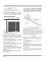
Fig. 2) then withdraw retaining screw A and lift out the grille.
Unhook the assembly containing
CI701
and R1702 and
remove
the four securing nuts from the
corners
cf the shield
which may
then be withdrawn. The degaussing coils may be released from
the
shield by bending back the retaining tabs. Fit the new coils
to
the
shield and clamp them by bending
over
each tab, then solder the
coil leads to the respective tag strip.
When
reassembling the shield,
ensure that spacers, washers and nuts are assembled in the correct
order (see Fig. 3).
Fig. 3. Assembly of C.R.T. and shield
SC 3809
Fig. 2. Removing convergence cover
3 .
T o l o w e r c h a s s i s
Remove two self-tapping screws from the top of the chassis, then
swing back the chassis to the extent of the securing lead.
4 .
Removal of the tuner assembly
Unplug the I.F. lead and two fly-leads connecting the tuner to the
receiver. Loosen three screws securing the aerial panel to the
mounting bracket on the chassis and detach the panel. Release the
single fixing screw from the tuner mounting bracket after which the
tuner, complete with leads, may be withdrawn from the cabinet.
5 .
Removal of the control panel
Pull off three control knobs and release four screws from the rear
of the control panel. The panel (still attached by its connecting
leads) may now be withdrawn from the cabinet.
6 .
Removal of the convergence unit
Remove four 4BA nuts and shake-proof washers from the corners
of the convergence control panel. The panel (still attached by its
leads) may now be withdrawn from the cabinet.
7 .
Replacement of degaussing coils L1723/4
Remove the main chassis, tuner assembly, control panel and con-
vergence unit together with the convergence yoke, deflection coils
and blue lateral unit. Lay the cabinet face downwards, supported
at each corner to prevent the C.R.T. taking the weight of the cabinet.
8.
Removal of the C.R.T.
WARNING
Extreme care must be taken when handling the C.R.T. and all safety
precautions must be taken.
Carry out the procedure as stated above for degaussing coil re-
placement. When the metal shield has been withdrawn, the C.R.T.
may be lifted away from the cabinet.
Note.
When the chassis, deflection coils, etc., have been re-assem-
bled, the receiver should be allowed to warm up for at least
20 minutes before any convergence or chroma. adjustments are
attempted. The blue lateral shift assembly should be fitted on the
C.R.T. neck with its shift magnets horizontal, and the lead tags
pointing to the base of the tube. The whole assembly must be
mounted as close to the convergence yoke as possible, allowi e -
sufficient space for the purity rings to be turned.
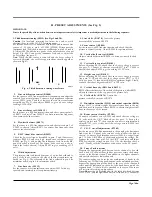
G — L.O.P.T. ASSEMBLY
Before replacing any valves, components, etc., in the L.O.P.T.
assembly, the anode cap of the C.R.T. should be disconnected and
short circuited to chassis to remove any residual charge remaining
on the tube.
1.
PL509 and PY500 removal
Unclip the wire cage top cover, pull off the top cap connections
then remove the valves.
2.
E Y 5 1 r e m o v a l
Unclip the wire
cage top cover and remove the lower side plate
(2 screws at the back of the plate). Unsolder the three leads from
the valve to the tag panel, then fit a new valve. When replacing the
side plate, ensure that the focus panel
lug
seats correctly in the slot
in the metal side plate.
3.
P D 5 0 0 r e m o v a l
Remove the main metal side plate (6 screws). Loosen the four
screws securing the top plate together with the valve base, and
slide the plate upwards to allow the valve to be withdrawn from
its holder.
121
•
MOUNTING BRACKET FZR
DEGAUSSING SHIELD
12 mm
122
123
119'
CRT. FIXING
BRACKET
117
- - - - - -
C A B I N E T
FRONT
/
115
120
/
1
,
21.
SD 3933
Page Six
Summary of Contents for G22K511
Page 3: ...G22K511 G25K512 Page Two ...
Page 12: ...Page Ten ...
Page 14: ...Page Eleven ...
Page 19: ...Page Fifteen ...


