


PARTS LIST + DISASSEMBLY ADVICE STAND
Pos
Service Nummer
Tray rubber foot for fi xation
Complete tray
Safety cap for boiler
Filling hole gasket for alu boiler
Superior stand printed
22
23
24
25
26
9965 000 08193
9965 000 08194
9965 000 08195
9965 000 01782
9965 000 08252
27
28
29
30
31
32
33
34
35
36
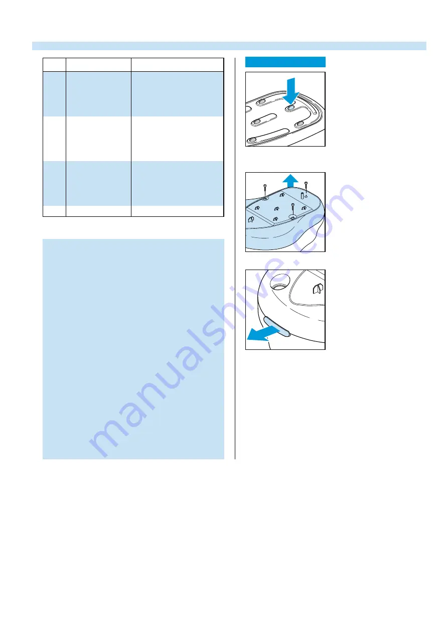
OPEN THE STAND
pressure fi xation rubber through
the tray
E
E
E
remove SCREW E (3 x)
remove LOCKED INSERT 29
NOTE:
OPEN NOW THE STAND.
DON’T WORRY IF THE SNAPS AT THE SIDE WILL BE
BROKEN.
THEY ARE ONLY FOR THE ASSEMBLY.
THE STAND REMAINS CLOSE WITHOUT THESE SNAPS.
ADJUSTMENT AND CONTROLS
– To avoid leakage of the sealings and damage to
the components in and on the boiler, NEVER clean
the boiler with vinegar, a descaling agent or other
chemicals.
– The boiler doesn’t contain serviceable parts.
Never disassemble the boiler body and /or
components on and in the boiler.
– ALWAYS REPLACE THE BOILER ( 28 ) WHEN:
*
the mechanical safety valve ( 24 ) has been
activated.
*
the boiler thermostat or hand - resettable safety
thermostat are open, because the boiler has
been subjected to too high temperatures.
*
the electrovalve ( 33 ) fails or the sieve is soiled
with scale.
– After the product has been repaired, it should
function properly and has to meet the safety
requirements as laid down and offi cially established
at this moment.
Description
4822 462 71999
9965 000 08240
9965 000 08201
9965 000 08202
9965 000 01790
Boiler rubber feet
Complete boiler
Locket insert
Inferior stand
Filter
9965 000 08203
4822 218 11561
9965 000 08241
9965 000 01900
9965 000 01902
Main switch
Electrovalve
Steam dial
Sream regulator
Steam ready light
37
9965 000 08246
Funnel


