background image

GC6103

2-6

DISASSEMBLY ADVICE - IRON

BACKPLATE 5

SWIVEL 14

Remove 

screw A

Disassemble 

BACKPLATE 5

Remove 

screw B (2x)

Remove 

cord clamp

INLAY 6

STEAM KNOB 7

MICROSWITCH 12

Remove 

screw A

Disassemble 

BACKPLATE 5

Disassemble 

INLAY 6

TEMPERATURE DIAL 1

IRON LAMP ASSY 10

IRON HANDLE 13

IRON COVER 16

SOLEPLATE MTD ASSY 17

Remove 

screw A

Disassemble 

BACKPLATE 5

Disassemble 

INLAY 6

Disassemble 

TEMPERATURE DIAL 1

Remove 

screw C (2x)

Disassemble 

IRON HANDLE 13

Remove 

screw D (3x)

Disassemble 

IRON COVER 16

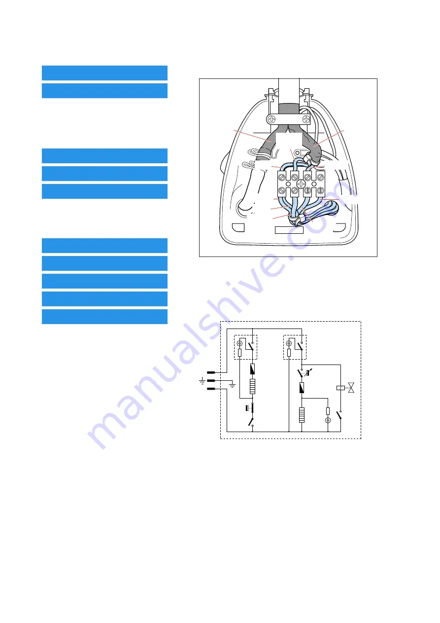
Hose-cord Assembly Connections

Hose

Cord

Blue

Yellow/

Green

Brown

Yellow/
Green

Blue

White

Brown

Yellow


Electrical Diagram

Boiler
Heating
Element

Boiler
Switch

Iron
Switch

Thermo-
fuse

Thermo-
fuse

Iron
Heating
Element

T (100˚C)
Thermostat

Thermostat

Micro-
switch

P (3.0 Bar)
Pressostat

Electro-
valve

L

N

Summary of Contents for GC6103

Page 1: ...ight switch Safety Information This product meets the requirements regarding interference suppression on radio TV Due to the high wattage of the iron only the specified cord set must be used After the product has been repaired it should function properly and has to meet the safety requirements legal regulations as laid down officially established at this moment TECHNICAL INFORMATION Voltage 230 V ...

Page 2: ...OLEPLATE MTD ASSY 17 Remove screw A Disassemble BACKPLATE 5 Disassemble INLAY 6 Disassemble TEMPERATURE DIAL 1 Remove screw C 2x Disassemble IRON HANDLE 13 Remove screw D 3x Disassemble IRON COVER 16 Hose cord Assembly Connections Hose Cord Blue Yellow Green Brown Yellow Green Blue White Brown Yellow Electrical Diagram Boiler Heating Element Boiler Switch Iron Switch Thermo fuse Thermo fuse Iron H...

Page 3: ...510 4239 022 55520 Temperature dial Thermostat bush Sliding probe Sound spring Backplate Inlay Steam knob Fix piece Steam knob spring Iron lamp assy Pos Service code Description 11 12 13 14 15 16 17 18 19 4239 022 55410 4239 022 55500 4239 022 55390 4239 022 55440 4239 022 55490 4239 022 55340 4239 022 55360 4239 022 55460 4239 022 55070 Iron lamp cover Microswitch Iron handle Swivel Small termina...

Page 4: ...e When replacing HOSE CORD ASSY 40 please refer to IMPORTANT directives in the REPAIR INSTRUCTIONS on page 6 Pos Service code Description 20 21 22 23 24 25 26 29 30 31 34 4239 022 55630 4239 022 55640 4239 022 55560 4239 022 55550 4239 022 55650 4239 022 55660 4239 022 55570 4239 022 55600 4239 022 55840 4239 022 55720 4239 022 55850 Silicon cap A Silicon cap B Heat insulation plate Top cover Whit...

Page 5: ...GC6103 5 6 EXPLODEDVIEW BOILER STAND 20 23 35 37 38 34 24 31 25 40 43 41 E 4x F 4x J 3x G 5x 21 42 36 39 36 26 22 29 30 47 ...

Page 6: ...efore it is returned to the consumer 1 Soleplate temperature Check that soleplate temperature is within IEC requirement Measure the temperature of the soleplate after the iron has reached steady state i e connected to the mains for at least 15 minutes The table below shows the temperature requirement Marking Soleplate temperature Deg C Material for example Test point Minimum Maximum Nominal Tolera...

Reviews: