background image

GC6360

2-6

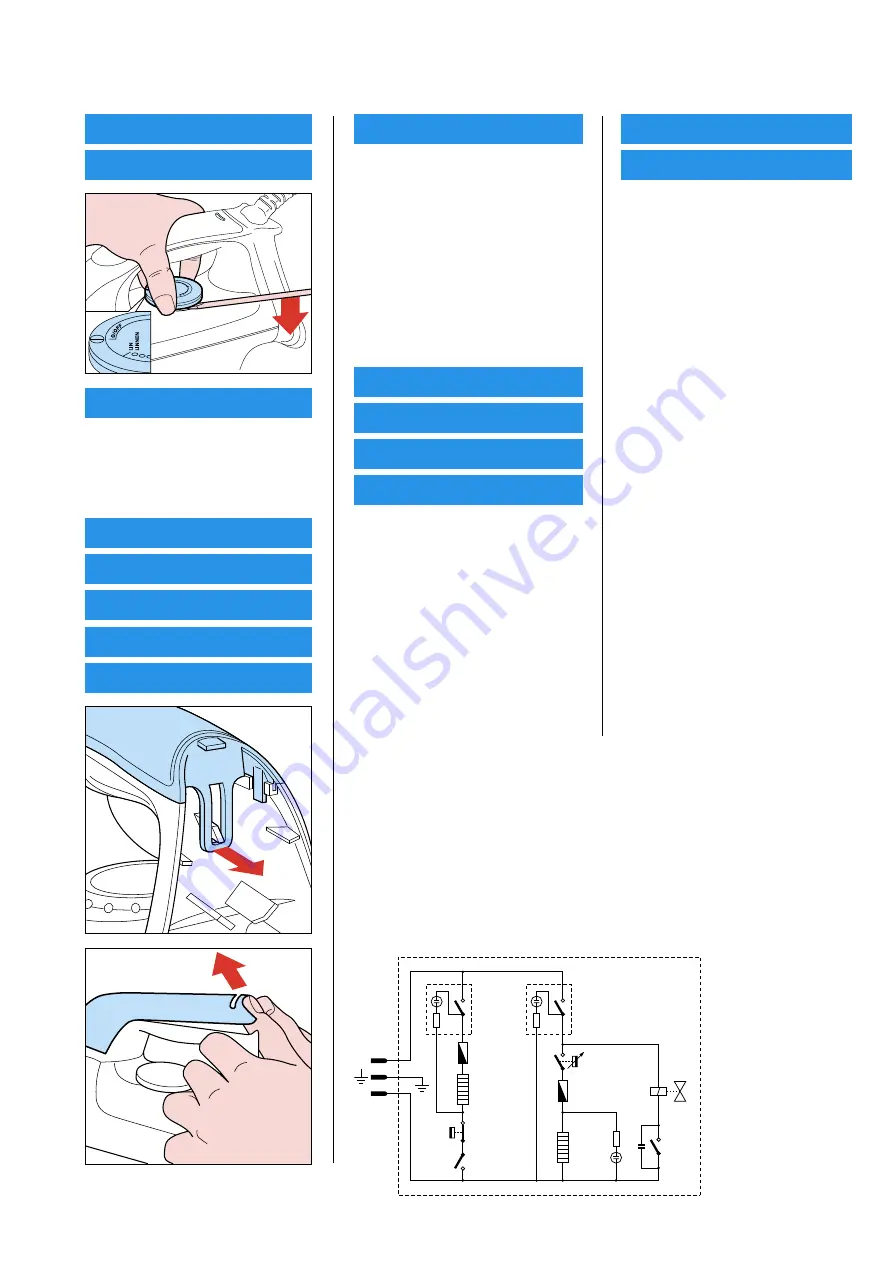
DISASSEMBLY ADVICE - IRON

THERMOSTAT DIAL 1

RATTLE SPRING 13

BACKPLATE 2

Disassemble 

DIAL 1

Remove 

Screw A

Remove 

Connection

Remove 

Hose

INLAY (SOS) 3

SOS KNOB 14

TRIGGER 12

IRON LAMP ASSY 4

MICRO SWITCH 5

REPAIR INSTRUCTIONS

-  For disassembly, you will need a Torx screwdriver: 362 TR T20 x 100

OPTIONAL (accessories)

-  No specific issues

Electrical Diagram

Boiler
Heating
Element

Boiler
Switch

Iron
Switch

Thermo-
fuse

Thermofuse

Iron
Heating
Element

T (100˚C)
Thermostat

Thermostat

Micro-
switch

Pressostat

Electro-
valve

L

N

C

HANDLE PRINTED 6

Disassemble 

DIAL 1

Remove 

Screw A

Remove 

Connection

Remove 

Hose

Disassemble 

BACKPLATE 2

Disassemble 

INLAY (SOS) 3


SOS KNOB 14


IRON LAMP ASSY 4


MICRO SWITCH 5

Remove 

Screws B (3 x)

HOSE-CORD ASSY  7

SWIVEL 8

STEAM DEVIAOR 15

THERMOSTAT BUSH 9

Disassemble 

DIAL 1

Remove 

Screw A

Remove 

Connection

Remove 

Hose

Disassemble 

BACKPLATE 2

Disassemble 

INLAY (SOS) 3


SOS KNOB 14


IRON LAMP ASSY 4


MICRO SWITCH 5

Remove 

Screws B (3 x)

Disassemble 

HANDLE PRINTED 6

IRON COVER SPRAYED 10

SOLEPLATE ASSY  11

Disassemble 

DIAL 1

Remove 

Screw A

Remove 

Connection

Remove 

Hose

Disassemble 

BACKPLATE 2

Disassemble 

INLAY (SOS) 3


SOS KNOB 14


IRON LAMP ASSY 4


MICRO SWITCH 5

Remove 

Screws B (3 x)

Disassemble 

HANDLE PRINTED 6

Disassemble 

HOSE-CORD ASSY 7


SWIVEL 8


STEAM DEVIATOR 15


THERMOSTAT

 BUSH 

9

Remove 

Screws C (3 x)

Summary of Contents for GC6360

Page 1: ...mp Boiler empty pilot lamp Safety Information This product meets the requirements regarding interference suppression on radio TV Due to the high wattage of the iron only the specified cord set must be used After the product has been repaired it should function properly and has to meet the safety requirements legal regulations as laid down officially established at this moment TECHNICAL INFORMATION...

Page 2: ... Remove Screw A Remove Connection Remove Hose Disassemble BACKPLATE 2 Disassemble INLAY SOS 3 SOS KNOB 14 IRON LAMP ASSY 4 MICRO SWITCH 5 Remove Screws B 3 x HOSE CORD ASSY 7 SWIVEL 8 STEAM DEVIAOR 15 THERMOSTAT BUSH 9 Disassemble DIAL 1 Remove Screw A Remove Connection Remove Hose Disassemble BACKPLATE 2 Disassemble INLAY SOS 3 SOS KNOB 14 IRON LAMP ASSY 4 MICRO SWITCH 5 Remove Screws B 3 x Disas...

Page 3: ... 4239 017 09170 4239 021 38130 4239 021 39420 4239 026 15580 4239 026 13220 4239 026 25680 4239 021 38110 4239 026 25760 4239 014 54060 4239 026 25710 4239 021 19620 4239 015 55710 Thermostat dial printed Eng Fre Backplate Inlay SOS Iron lamp assy Microswitch Handle printed Hose cord assy Microswitch Swivel Thermostat bush Iron cover Soleplate assy CSC 230 V Trigger Rattle spring SOS knob Steam de...

Page 4: ... please refer to IMPORTANT directives in the REPAIR INSTRUCTIONS on page 6 Pos Service code Description 20 21 22 23 24 25 26 27 28 29 30 31 32 4239 022 57780 4239 022 57790 4239 022 55560 4239 022 57800 4239 022 57810 4239 022 55660 4239 022 57820 4239 022 57830 4239 022 57840 4239 022 55600 4239 022 55840 4239 022 55720 4239 022 55700 Silicon cap A Silicon cap B Heat insulation plate Top cover Sa...

Page 5: ...GC6360 5 6 EXPLODEDVIEW BOILER STAND 27 20 43 26 22 23 35 37 38 33 32 18 34 24 31 25 46 41 28 44 45 29 E 4x F 4x H 2x J 3x G 5x 30 21 42 18 36 39 36 47 ...

Page 6: ...efore it is returned to the consumer 1 Soleplate temperature Check that soleplate temperature is within IEC requirement Measure the temperature of the soleplate after the iron has reached steady state i e connected to the mains for at least 15 minutes The table below shows the temperature requirement Marking Soleplate temperature Deg C Material for example Test point Minimum Maximum Nominal Tolera...

Reviews: