GC6360
4-6
DISASSEMBLY ADVICE & PARTS LIST - BOILER STAND
HEAT INSULATION PLATE 22
TOP COVER 23
BOILER MOUNTED ASSY 31
Remove
screw G (5x)
Disassemble
TOP COVER 23
Straighten ear locks of Heat Insulation Plate
Disassemble
HEAT INSULATION
PLATE
22
FACE PLATE 26
LIGHT SWITCH HOLDER 29
LIGHT SWITCH 30
STEAM REGULATOR 33
Remove
screw G (5x)
Disassemble
TOP COVER 23
Remove
screw E (4x)
Disassemble
FACE PLATE 26
Remove
screw F (4x)
Disassemble
LIGHT SWITCH
HOLDER
29
Remove
screw H (2x)
Disassemble
STEAM REGULATOR 33
HOSE-CORD ASSY 40
POWER CORD 41
Remove
screw G (5x)
Disassemble
TOP COVER 23
Remove
screw J (3x)
Disassemble
STAND CORD
CLAMP
35
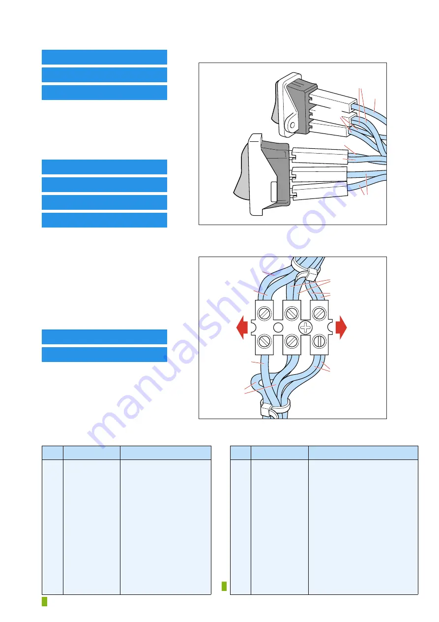
Connections on LIGHT SWITCH 30
Blue
Yellow
Iron
switch
Boiler
switch
Blue
Yellow/
Green
Brown
Brown
Connections on BIGTERMINAL BLOCK 34
BOILER
side
FACE
PLATE
side
Blue
Yellow
Brown
Brown
Blue
Yellow/
Green
Yellow/
Green
Note:
When replacing HOSE-CORD ASSY 40, please refer to IMPORTANT directives in the REPAIR INSTRUCTIONS on page 6.
Pos
Service code
Description
20
21
22
23
24
25
26
27
28
29
30
31
32
4239 022 57780
4239 022 57790
4239 022 55560
4239 022 57800
4239 022 57810
4239 022 55660
4239 022 57820
4239 022 57830
4239 022 57840
4239 022 55600
4239 022 55840
4239 022 55720
4239 022 55700
Silicon cap A
Silicon cap B
Heat insulation plate
Top cover
Safety cap assy (Leak pressure
valve + Relief valve cap)
Filling hole gasket
Face plate
Steam dial
Steam dial ring
Light switch holder
Light switch
Boiler mounted assy
Silicon hose (L = 140 mm)
Pos
Service code
Description
33
34
35
36
37
38
39
41
42
43
44
45
46
47
4239 022 55710
4239 022 55850
4239 022 55790
4239 022 55540
4239 022 57850
4239 022 57320
4239 022 55680
4239 022 57340
4239 022 55670
4239 022 57860
4239 022 55860
4239 022 55610
4239 022 55620
4239 022 58590
Steam regulator
Big terminal block
Stand cord clamp
Boiler foot
Bottom cover
Guard jacket
Stand foot
Power cord - EU
Cable tie
Stand assy - GC6360
Neon lamp
Neon lamp cover
Neon lamp holder
Safety valve sealing ring
= changed


