background image

GC6360

6-6

REPAIR INSTRUCTIONS

-  Due to the high wattage of the iron, only the specified cord set must be used.
-  Should damage be observed on the 

HOSE-CORD ASSY 40

 or 

POWER CORD 41

, they must be replaced. 

Continued usage is not allowed.
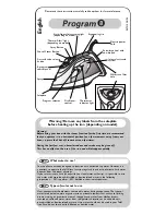
- When 

replacing 

HOSE-CORD ASSY 40

, it is 

IMPORTANT

 to ensure that the white silicon sleeve is held tightly by the 

cord clamp.  Below picture shows the correct position of the silicon sleeve with respect to the cord clamp.
Do also ensure that the orientation of the cord clamp is correct i.e. such that the round end is on the left & the flat end is on the 
right, as shown in the picture.

White silicon sleeve

Flat edge to be always 
on the cord side

Cord clamp

Cord

Hose

-  After the product has been repaired, it should function properly and has to meet the safety requirements & legal regulations as 

laid down & officially established at this moment.

-  The following tests are common checks that are conducted on a repaired product before it is returned to the consumer.
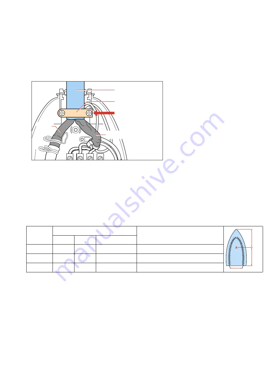
1. 

Soleplate temperature

Check that soleplate temperature is within IEC requirement.

Measure the temperature of the soleplate after the iron has reached steady state i.e connected to the mains for at least 15 minutes. 
The table below shows the temperature requirement.

Marking

Soleplate temperature (Deg C)

Material, for example

Test-
point

==

Minimum Maximum N Tolerance

 (1 

dot)

  70

120

  95 ± 25

Acetate, elastane, polyamide, polyproylene

••

 (2 

dots)

100

160

130 ± 30

Cupro, polyester, silk, triacetate, viscose, wool

•••

 (3 dots)

140

210

175 ± 35

Cotton, linen

2. 

Leakage current

Check that leakage current is within IEC requirement.

Measure leakage current between LIVE/NEUTRAL & EARTH.
IEC requirement is that at 230 V supply, the EARTH leakage current must be less than 0.75 mA.

3. 

Water leakage / Functionality

Check that there is no water leakage from any part of the product during operation.

Check that the functionality of the product (product dependent) eg. steaming, variable steam, SOS, ASO etc is working properly.

4. 

Loose part

Check that there are no loose parts eg. extra screw in the product that can cause short-circuit or product malfunction.

Summary of Contents for GC6360

Page 1: ...mp Boiler empty pilot lamp Safety Information This product meets the requirements regarding interference suppression on radio TV Due to the high wattage of the iron only the specified cord set must be used After the product has been repaired it should function properly and has to meet the safety requirements legal regulations as laid down officially established at this moment TECHNICAL INFORMATION...

Page 2: ... Remove Screw A Remove Connection Remove Hose Disassemble BACKPLATE 2 Disassemble INLAY SOS 3 SOS KNOB 14 IRON LAMP ASSY 4 MICRO SWITCH 5 Remove Screws B 3 x HOSE CORD ASSY 7 SWIVEL 8 STEAM DEVIAOR 15 THERMOSTAT BUSH 9 Disassemble DIAL 1 Remove Screw A Remove Connection Remove Hose Disassemble BACKPLATE 2 Disassemble INLAY SOS 3 SOS KNOB 14 IRON LAMP ASSY 4 MICRO SWITCH 5 Remove Screws B 3 x Disas...

Page 3: ... 4239 017 09170 4239 021 38130 4239 021 39420 4239 026 15580 4239 026 13220 4239 026 25680 4239 021 38110 4239 026 25760 4239 014 54060 4239 026 25710 4239 021 19620 4239 015 55710 Thermostat dial printed Eng Fre Backplate Inlay SOS Iron lamp assy Microswitch Handle printed Hose cord assy Microswitch Swivel Thermostat bush Iron cover Soleplate assy CSC 230 V Trigger Rattle spring SOS knob Steam de...

Page 4: ... please refer to IMPORTANT directives in the REPAIR INSTRUCTIONS on page 6 Pos Service code Description 20 21 22 23 24 25 26 27 28 29 30 31 32 4239 022 57780 4239 022 57790 4239 022 55560 4239 022 57800 4239 022 57810 4239 022 55660 4239 022 57820 4239 022 57830 4239 022 57840 4239 022 55600 4239 022 55840 4239 022 55720 4239 022 55700 Silicon cap A Silicon cap B Heat insulation plate Top cover Sa...

Page 5: ...GC6360 5 6 EXPLODEDVIEW BOILER STAND 27 20 43 26 22 23 35 37 38 33 32 18 34 24 31 25 46 41 28 44 45 29 E 4x F 4x H 2x J 3x G 5x 30 21 42 18 36 39 36 47 ...

Page 6: ...efore it is returned to the consumer 1 Soleplate temperature Check that soleplate temperature is within IEC requirement Measure the temperature of the soleplate after the iron has reached steady state i e connected to the mains for at least 15 minutes The table below shows the temperature requirement Marking Soleplate temperature Deg C Material for example Test point Minimum Maximum Nominal Tolera...

Reviews: