GC6602
2-7
Disassembly advice - Iron
BUTTON 27
TOP COVER 20
CORD BUSHING 21
CONTROL & POWER PCBA 1, 23
STEAM KNOB 4
DIAL KNOB 19
CORD CLAMP 18
HOUSING 5
POTENTIOMETER BOX 17
STEAM TUBE CONNECTOR 8
Remove
Screw A1, A2
Remove
BUTTON 27
Remove
Screw B1
Remove
TOP COVER 20
Remove
Screw C1
Remove
CORD BUSHING 21
Remove
CONTROL & POWER PCBA 1,23
Remove
STEAM KNOB 4
Remove
Screw D1
Remove
DIAL KNOB 19
Remove
Screw E1, E2
Remove
CORD CLAMP 18
Remove
HOUSING 5
Remove
Screw F1, F2
Remove
POTENTIOMETER BOX 17
Remove
Screw G1, G2, G3
Remove
STEAM TUBE CONNECTOR 8
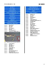
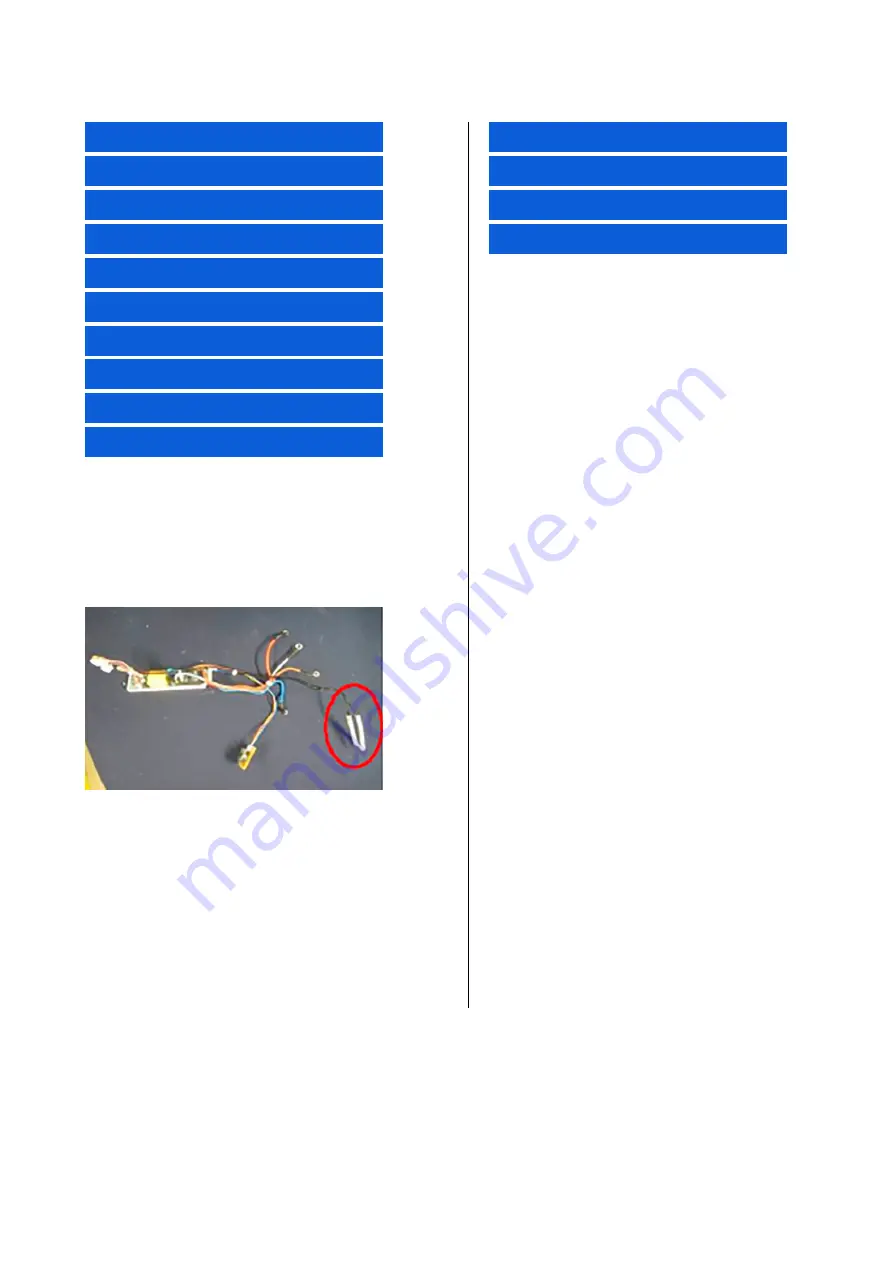
Fig 1: Thermistor is part of the Power PBCA Asm
WIRE CONNECTOR 29
CONNECTION WIRE ASM 28
BASE 9
SOLEPLATE ASSY 11
Remove
Screw A1, A2
Remove
BUTTON 27
Remove
Screw B1
Remove
TOP COVER 20
Remove
Screw C1
Remove
CORD BUSHING 21
Remove
CONTROL & POWER PCBA 1,23
Remove
STEAM KNOB 4
Remove
Screw D1
Remove
DIAL KNOB 19
Remove
Screw E1, E2
Remove
CORD CLAMP 18
Remove
HOUSING 5
Remove
Screw F1, F2
Remove
POTENTIOMETER BOX 17
Remove
Screw G1, G2, G3
Remove
STEAM TUBE CONNECTOR 8
Remove
Screw H1, H2, H3, H4
Remove
WIRE CONNECTOR 29
Remove
CONNECTION WIRE ASM 28
Remove
BASE 9
Remove
SOLEPLATE ASSY 11


