background image

GC6602

4-7

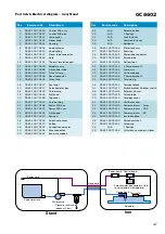
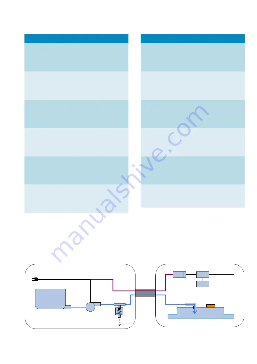
Power cord

Hose cord

Power board

Dosing head

Soleplate

Thermistor

Control board

Fixed water tank

Stand

Iron

Water pump

Pressure relief valve
(opens at 2 bar)

Potentiometer (connected to T-dial
to set soleplate’s temperature)

Part lists & Electrical diagram - Iron/Stand   

Pos

Service code

Description

  1

  2

  3

  4

  5

9965 100 73639

9965 100 70251

9965 100 70211

9965 100 70201

9965 100 70241

Control PCB assy

Control PCB box

Lamp cover

Steam knob

Housing

  6

  7

  8

  9

10

9965 100 70238

9965 100 70215

9965 100 70223

9965 100 70218

9965 100 70202

Knob cylinder

Knob spring

Steam tube connector

Base

Thermal insulation pad

11

12

13

14

15

9965 100 70249

9965 100 70198

9965 100 70224

9965 100 70246

9965 100 70203

Soleplate assy

Silicon fi ber tube

Throat clamp

Bend connector

Throat clip

16

17

18

19

20

9965 100 70237

9965 100 70227

9965 100 70247

9965 100 70242

9965 100 70199

Seal ring 1

Potentiometer box

Cord clamp

Dial knob

Top cover

21

22

23

24

25

9965 100 70214

9965 100 70208

9965 100 73641

9965 100 70225

9965 100 70239

Cord bushing

Power PCB box

Power PCB asm

Silicon pad

Spring 4

26

27

28

29

30

9965 100 70194

9965 100 70197

9965 100 70207

9965 100 70228

9965 100 70231

Switch hole cover

Button

Connection wire asm

Wire connector

Iron base support

Pos

Service code

Description

31

32

33

34

35

N/A

N/A

N/A

N/A

N/A

Release button

2 Spring 2

Lock fastener

Location fastener

Bolt base

36

37

38

39

40

9965 100 70236

9965 100 70226

9965 100 70243

9965 100 70196

9965 100 70206

Water tank asm

Seal ring

Water tube connector

Silicon tube

Bottom foot

41

42

43

44

45

9965 100 70216

9965 100 70245

9965 100 70234

9965 100 70248

9965 100 70205

2 Pump bracket 2

Pump assy

Unit base body

1 Pump bracket 2

Cord clamp

46

47

48

49

50

9965 100 70222

9965 100 70217

9965 100 70195

9965 100 70219

9965 100 70213

Terminal block

Switch bracket & Rocker switch

Safety valve asm

Silicon tube

Cord box cover

51

52

52

52

55

9965 100 70221

9965 100 70209

9965 100 70212

9965 100 70229

9965 100 70244

Unit base cover

Power cord asm - Swiss

Power cord asm - VDE

Power cord asm - BS

Insulation base

56

57

58

59

9965 100 70204

9965 100 70235

N/A

9965 100 71433

Silicon cushion 1

Screw cap

1 Spring 1

Calc clean container & sticker

Summary of Contents for GC6602

Page 1: ...compartment Cord freedom swivel 180 degree cord freedom Hose length 1 6 m Power cord length 1 8 m Calc management Suitable for tap water Calc clean solution Smart Calc Clean Calc clean reminder Filtered water recommended Safety Information This product meets the requirements regarding interference suppression on radio and TV After the product has been repaired it should function properly and has t...

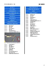
Page 2: ... Remove POTENTIOMETER BOX 17 Remove Screw G1 G2 G3 Remove STEAM TUBE CONNECTOR 8 Fig 1 Thermistor is part of the Power PBCA Asm WIRE CONNECTOR 29 CONNECTION WIRE ASM 28 BASE 9 SOLEPLATE ASSY 11 Remove Screw A1 A2 Remove BUTTON 27 Remove Screw B1 Remove TOP COVER 20 Remove Screw C1 Remove CORD BUSHING 21 Remove CONTROL POWER PCBA 1 23 Remove STEAM KNOB 4 Remove Screw D1 Remove DIAL KNOB 19 Remove S...

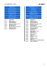
Page 3: ...ASSY 42 CORD CLAMP 45 CORD BOX COVER 50 TERMINAL BLOCK 46 SWITCH BRAKET ROCKER SWITCH 47 POWER CORD ASM 52 Remove SCREW CAP 57 Remove Screws A1 A2 Remove SILICON CUSHION 56 Remove INSULATION BASE 55 Remove Screws C1 C2 C3 C4 C5 C6 C7 Remove UNIT BASE COVER 51 Remove BOTTOM FOOT 40 Remove Screws D1 D2 D3 D4 D5 D6 D7 Remove WATER TANK ASM 36 Remove UNIT BASE BODY 43 Remove Screw E1 E2 Remove PUMP BR...

Page 4: ...00 70225 9965 100 70239 Cord bushing Power PCB box Power PCB asm Silicon pad Spring 4 26 27 28 29 30 9965 100 70194 9965 100 70197 9965 100 70207 9965 100 70228 9965 100 70231 Switch hole cover Button Connection wire asm Wire connector Iron base support Pos Service code Description 31 32 33 34 35 N A N A N A N A N A Release button 2 Spring 2 Lock fastener Location fastener Bolt base 36 37 38 39 40...

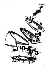
Page 5: ...GC6602 5 7 A2 A1 E1 H1 H2 H3 H4 E2 C1 D1 F2 F1 G1 G3 B1 G2 16 12 25 2 6 7 26 9 11 5 27 13 28 8 1 3 18 21 20 10 24 4 22 15 23 14 17 19 Exploded view Iron ...

Page 6: ...GC6602 6 7 A2 C2 C6 G1 H1 E1 D1 D2 D4 D5 D3 D6 D8 D7 E2 F1 F2 F4 F3 I1 I2 A1 C1 C3 C5 C7 C4 38 42 44 36 43 37 41 57 52 55 45 50 49 47 40 46 39 51 48 56 Exploded view Stand ...

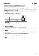
Page 7: ...st point Minimum Maximum 170 230 All fabric types 2 Leakage current Check that leakage current is within IEC requirement Measure leakage current between LIVE NEUTRAL EARTH IEC requirement is that at 230 V supply the EARTH leakage current must be less than 0 75 mA 3 Water leakage Functionality Check that there is no water leakage from any part of product during operation Check that the functionalit...

Reviews: