
GC7220
5-7
TRAY RUBBER CAP 30
TRAY ASSY 33
DOOR ASSY 35
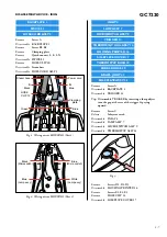
Remove
TRAY RUBBER CAP 30 (3x)
Remove
Screw F1, F2, F3
Disassemble
TRAY ASSY 33
Remove
Screw G
Disassemble
DOOR ASSY 35
FRONT PANEL PRINTED 37
POWER BOARD 43
LIGHT SWITCH 44
Remove
TRAY RUBBER CAP 30 (3x)
Remove
Screw F1, F2, F3
Disassemble
TRAY ASSY 33
Remove
Screw H1, H2
Disassemble
FRONT PANEL 37
Disassemble
LIGHT SWITCH 44
Disassemble
POWER BOARD 43
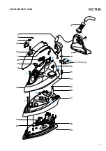
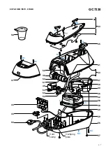
DISASSEMBLY ADVICE - STAND
WATER TANK ASSY 34
HOSE CORD CAP 36
BOILER ASSY 38
BRAIDED RUBBER HOSE -
BOILER 41
PUMP ASSY 45
INLET TUBE - PUMP 46
DE-AIR TUBE 47
RINSE RUBBER COUPLING 50
RINSE BUSH 51
RINSE CAP ASSY 52
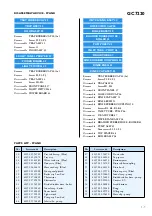
Remove
TRAY RUBBER CAP 30 (3x)
Remove
Screw F1, F2, F3
Disassemble
TRAY ASSY 33
Remove
Screw H1, H2
Disassemble
FRONT PANEL 37
Disassemble
HOSE CORD CAP 36
Disassemble
RINSE CAP ASSY 52
Disassemble
RINSE BUSH 51
Disassemble
RINSE RUBBER COUPLING 50
Remove
Screws K1, K2, K3, K4
Disconnect
INLET TUBE - PUMP 46
Disconnect
DE-AIR TUBE 47
Disassemble
WATER TANK ASSY 34
Disassemble
BRAIDED RUBBER HOSE - BOILER 41
Disassemble
PUMP ASSY 45
Remove
Torx screws L1, L2, L3
Disassemble
TOP SPACER 48
Disassemble
BOILER ASSY 38
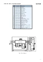
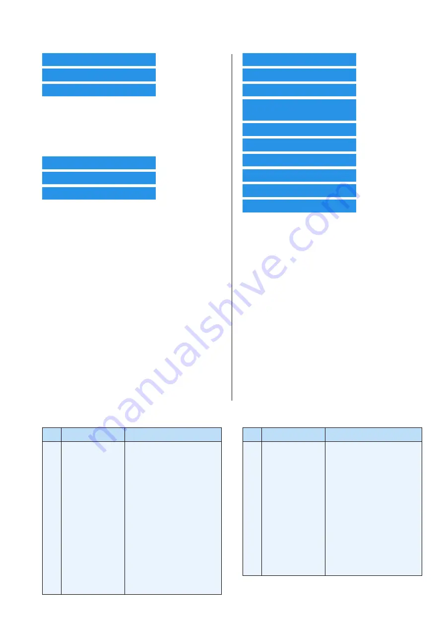
PARTS LIST - STAND
Pos
Service code
Description
30
33
34
35
36
37
38
39
40
41
42
43
44
45
46
4239 015 56780
4239 021 39670
4239 021 42140
4239 021 40140
4239 026 26410
4239 021 41000
4239 021 39530
4239 017 10420
4239 017 09890
4239 015 56930
4239 010 10260
4239 021 40330
4239 017 10510
4239 021 39720
4239 015 56860
Tray rubber cap (Blue)
Tray assy
Water tank assy (Blue)
Door assy (Blue)
Hose cord cap (Blue)
Front panel printed
Boiler assy Low End
Thermistor
Electrovalve
Braided rubber hose - boiler
Inox clamp - boiler
Power board
Light switch
Pump assy Low End
Inlet tube - pump
Pos
Service code
Description
47
48
49
50
51
52
53
54
55
56
57
58
59
4239 015 56870
4239 026 26120
4239 026 26110
4239 015 56760
4239 026 26130
4239 021 39570
4239 010 10600
4239 015 56880
4239 000 10100
4239 026 26080
4239 015 52340
4239 026 05990
4239 010 10610
De-air tube
Top spacer
Bottom spacer
Rinse rubber coupling
Rinse bush
Rinse cap assy (Blue)
Inox clamp - pump
Braided rubber hose - pump
Cordset EU
Stand bottom
Bung
Filling cup
Hose clip - pump


