background image

Published by Philips Consumer Lifestyle                                    | 

P a g e




For internal use only 

Document No. : CSW-07-081-18111 


Product Information (Continue) 

Wiring Diagram - Iron


Summary of Contents for GC8930

Page 1: ...Published by Philips Consumer Lifestyle 1 P a g e For internal use only Document No CSW 07 081 18111 PERFECT CARE EXPERT PLUS STEAM GENERATOR GC 8930 GC 8940 GC8942 GC8950 GC8952 GC 8960 GC 8962 ...

Page 2: ... Document No CSW 07 081 18111 Contents Page 1 Important Repair Instructions 3 2 Product Information Product Matrix 6 Functions Features Information 7 Wiring Diagram 8 3 Troubleshooting 10 4 Disassembly and Reassembly Instructions 12 5 Service Parts 24 6 Revision History 37 ...

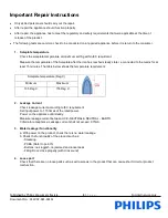
Page 3: ...steady state i e connected to the mains for at least 15 minutes The table below shows the temperature requirement Soleplate temperature Deg C Minimum Maximum 135 Deg C 155 Deg C 2 Leakage Current Check leakage current according to IEC requirement Set input power to 1 15 times of the rated power Power on the appliance until steady Measure leakage current between LIVE NEUTRAL NEUTRAL EARTH Criteria ...

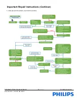
Page 4: ... 5 2 Reset product to Factory Mode Test FMT Flow Start Remove water tank Press and hold Power and ECO buttons Turn on mains power Plug in mains cord without releasing buttons Tank Empty LED Amber turns on YES Tank Empty LED will remain on for 3 secs Release Power button YES NO Turn off mains power Unplug in mains cord Wait for at least 5 secs Is time 3 secs NO Press and release the steam trigger t...

Page 5: ...Published by Philips Consumer Lifestyle 5 P a g e For internal use only Document No CSW 07 081 18111 Important Repair Instructions Continue 5 3 Process Self Check Mode start Self Check Mode ...

Page 6: ... 7 7 5 7 5 7 5 Steam Boost g 450 470 480 500 520 500 520 Optimal TEMP Yes Yes Yes Yes Vertical Steam Yes Yes Yes Yes Steam Ready Time min 2 2 2 2 Soleplate Coating SteamGlide Advanced SteamGlide Advanced SteamGlide Advanced SteamGlide Advanced Anti Calc Easy de calc Easy de calc Easy de calc Easy de calc ECO Yes Yes Yes Yes Turbo Yes Yes Yes Yes Water Tank ml 1800 1800 1800 1800 Carry Lock Yes Yes...

Page 7: ...chnology Lower water level alarm for GC8960 8962 only Heat up time 2 min Vertical Steam Safety auto off Variable Steam Settings Light and comfortable Steam Output Control Open handle Steam Tip Safe for all fabrics Even for delicates such as Steam on demand silk material Cord freedom Swivel 180 degree Calc Management Storage Suitable for tap water Storage Calc Clean solution Easy De Calc Storage so...

Page 8: ...Published by Philips Consumer Lifestyle 8 P a g e For internal use only Document No CSW 07 081 18111 Product Information Continue Wiring Diagram Iron ...

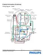
Page 9: ...Published by Philips Consumer Lifestyle 9 P a g e For internal use only Document No CSW 07 081 18111 Product Information Continue Wiring Diagram Stand ...

Page 10: ... Change Power PCBA Mainscord Change Mainscord Steam trigger pressed does not detected refer to page 5 Hose cord Assy connection Reconnect retest Iron LED Assy Change Iron LED Assy Hose Cord Assy Change Hose Cord Assy E Valve Change E Valve Trigger Change Trigger Power PCBA Change Power PCBA Water leaking from De Calc area Rinse Cap Assy engagement Tighten and retest Rinse Cap Assy Change Rinse Cap...

Page 11: ...e Fast Blink 400ms OFF Iron Thermistor Short Circuit ECO Power Tank LED scrolling clockwise OFF Iron Thermistor Open Circuit ECO Power Tank LED scrolling anti clockwise OFF Boiler Thermistor Short Circuit ECO Turbo Tank LED scrolling clockwise OFF Boiler Thermistor Open Circuit ECO Turbo Tank LED scrolling anti clockwise OFF Error Detected Over Heat Thermistor Error ECO LED Power LED Tank LED ECO ...

Page 12: ...g Prted 4 9 Remove Mica Washer 2 Remove Screw B from Chassis 7 10 Remove Housing Prted 4 3 Remove Inlay 2K Assy 1 11 Remove Screw E from Chassis to Soleplate 4 Remove Screw C from Micro Switch LED Assy 12 Remove Screw F 5 Remove Iron LED Assy 2 13 Disconnect all wire connection 6 Remove Micro Switch LED Holder 3 14 Remove Chassis 7 7 Remove Trigger 5 Trigger Spring 15 Remove Hose Clip 8 Remove Scr...

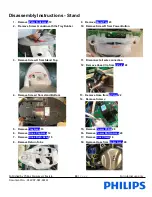
Page 13: ... Remove Screw R from Power Button 3 Remove Screw H from Stand Top 11 Disconnect all wire connection 12 Remove Hose Clip from E Valve 22 4 Remove Screw I from stand Bottom 13 Remove Hose from E Valve 22 14 Remove Screw J 5 Remove Tray Assy 13 15 Remove Power PCBA 28 6 Remove Rinse Cap Assy 14 16 Remove Power Button Assy 29 7 Remove Rinse Bush Assy 15 17 Remove Inox Clamp 18 8 Remove Return Tube 18 ...

Page 14: ...ly Instructions Stand 19 Remove Screw L 25 Remove Screw N 20 Remove Spacer Top 17 26 Remove Clamping Plate 21 Remove Boiler Assy 20 27 Disconect all wire connection 22 Remove Screw M 28 Remove Mainscord 30 23 Remove Inlet Coupling Assy 29 Remove Hall Sensor PCBA 26 24 Remove Spacer Bottom 30 Remove Pump Assy 19 ...

Page 15: ...tyle 15 P a g e For internal use only Document No CSW 07 081 18111 Disassembly Instructions Lock Assy Step 1 Use a screw driver to lift up the spring in the Lock Assy Step 2 Remove the lifted spring Step 3 Slide and lift up the Lock Assy ...

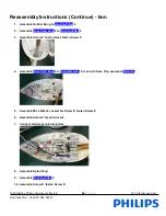
Page 16: ...Assemble Hose Cord Assy 6 to Housing Prted 4 3 Assemble Screw P on Grommet fasten Screw P 4 Assemble Hose Cord Assy 6 to Soleplate Assy 8 lock with Hose Clip assemble Chassis 7 5 Assemble Mica Washer assemble Screw E fasten Screw E 6 Assemble Screw F fasten Screw F 7 Connect all wire per picture below 8 Assemble Ryton Ring 9 Assemble Housing Prted 4 10 Assemble Screw D fasten Screw D ...

Page 17: ... to Housing Prted 4 14 Assemble Screw E fasten Screw E 15 Connect wire Micro Switch to Hose Cord 16 Assemble Inlay 2K Assy 1 17 Assemble Screw A fasten Screw A 18 Assemble Screw B Fasten Screw B Cautions a before fastening screw relocate the screw with first thread Once done fasten the screw b Do not drop hit or knock the ASO PCBA ESD wrist strap proper pack with ESD bag c Ensure there is click so...

Page 18: ...ble Screw K fasten Screw K 3 Assemble Mainscord 30 4 Assemble Clamping Plate assemble Screw N fasten Screw N 5 Assemble Pump Assy 19 dress corrugated Tube to Stand Bottom Assy 27 6 Assemble Spacer Bottom 21 assemble Boiler Assy 20 7 Connect all wire 8 Assemble Hall Sensor PCBA 26 and dress wire 9 Connect Hose to E Valve 22 Lock Hose Clip with long nose plyer Dress Corrugated Tube inside the hook ...

Page 19: ... 29 assemble Screw J fasten Screw J 13 Assemble Screw R fasten Screw R 14 Assemble Power PCBA 28 Button Assy 29 connect dress wiring as shown 15 Assemble Inlet Coupling Assy 25 Inlet Coupling Seal 24 Connect Corrugated Tube 16 Assemble Screw M fasten Screw M 17 Assemble Stand Top 23 Connect Return Tube to Front Lock Bracket Assy 11 18 Assemble Tank Catch 16 Tank Catch Spring 19 Assemble Front Lock...

Page 20: ... I fasten Screw I 23 Assemble Rinse Bush Assy 15 24 Assemble Rinse Cap Assy 14 25 Assemble Water Tank Assy 10 Cautions d before fastening screw relocate the screw with first thread Once done fasten the screw e Do not drop hit or knock the ASO PCBA ESD wrist strap proper pack with ESD bag f Ensure there is click sound after Connector to Terminal engagement for wire connection ...

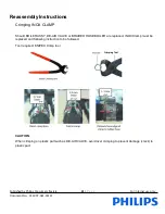
Page 21: ...ns Crimping INOX CLAMP Should BOILER ASSY DE AIR VALVE or BRAIDED HOSE BOILER are replaced INOX Clamp must be replaced and following instruction to be followed Tool required KNIPEX Crimp tool CAUTION When crimping on plastic part such as DE AIR VALVE avoid over crimping to prevent damage crack to plastic part Crimping Tool ...

Page 22: ...ECTROVALVE To prevent damage to the ELECTROVALVE during service activity the following to be observed during disassembly assembly Tool required Torque wrench set to 6Kgf CAUTION 1 The torque wrench engagement is allowed ONLY at the yellow box locations in below picture CAUTION 2 Ensure torque wrench jaw does not contact the solenoid body ...

Page 23: ... per below instruction to ensure matching of both hardware a For PCBA replacement To cut the jumper wires J1 J2 on PCBA based on the pump label as in Table 1 below b For pump replacement Table 1 Jumper wires on PCBA Label on Pump Pump label Jumper wire to cut on PCBA 1 J1 Pump 1 2 J2 Pump 2 J2 J1 Pump spoilt YES Change Pump Same Pump available YES Change PCBA YES YES Replace Pump accordingly Cut J...

Page 24: ... 13 TRAY ASSY 4239 022 74641 4239 022 74881 4239 022 74881 4239 022 74881 14 RINSE CAP ASSY 4239 022 74651 4239 022 74891 4239 022 74891 4239 022 74891 15 RINSE BUSH ASSY 4239 022 74661 4239 022 74661 4239 022 74661 4239 022 74661 16 TANK CATCH 4239 022 74671 4239 022 74671 4239 022 74671 4239 022 74671 17 SPACER TOP 4239 022 74681 4239 022 74681 4239 022 74681 4239 022 74681 18 INOX CLAMP 4239 02...

Page 25: ...TRAY ASSY 4239 022 74881 4239 022 74881 4239 022 75171 4239 022 75171 14 RINSE CAP ASSY 4239 022 74891 4239 022 74891 4239 022 74891 4239 022 74891 15 RINSE BUSH ASSY 4239 022 74661 4239 022 74661 4239 022 74661 4239 022 74661 16 TANK CATCH 4239 022 74671 4239 022 74671 4239 022 74671 4239 022 74671 17 SPACER TOP 4239 022 74681 4239 022 74681 4239 022 74681 4239 022 74681 18 INOX CLAMP 4239 022 74...

Page 26: ...RAY ASSY 4239 022 75171 4239 022 75171 4239 022 75171 4239 022 74981 14 RINSE CAP ASSY 4239 022 74891 4239 022 74891 4239 022 74891 4239 022 74991 15 RINSE BUSH ASSY 4239 022 74661 4239 022 74661 4239 022 74661 4239 022 75001 16 TANK CATCH 4239 022 74671 4239 022 74671 4239 022 74671 4239 022 74671 17 SPACER TOP 4239 022 74681 4239 022 74681 4239 022 74681 4239 022 74681 18 INOX CLAMP 4239 022 746...

Page 27: ...TRAY ASSY 4239 022 74981 4239 022 74981 4239 022 74981 4239 022 74981 14 RINSE CAP ASSY 4239 022 74991 4239 022 74991 4239 022 74991 4239 022 74991 15 RINSE BUSH ASSY 4239 022 75001 4239 022 75001 4239 022 75001 4239 022 75001 16 TANK CATCH 4239 022 74671 4239 022 74671 4239 022 74671 4239 022 74671 17 SPACER TOP 4239 022 74681 4239 022 74681 4239 022 74681 4239 022 74681 18 INOX CLAMP 4239 022 74...

Page 28: ...13 TRAY ASSY 4239 022 74981 4239 022 74981 4239 022 74981 4239 022 74981 14 RINSE CAP ASSY 4239 022 74991 4239 022 74991 4239 022 74991 4239 022 74991 15 RINSE BUSH ASSY 4239 022 75001 4239 022 75001 4239 022 75001 4239 022 75001 16 TANK CATCH 4239 022 74671 4239 022 74671 4239 022 74671 4239 022 74671 17 SPACER TOP 4239 022 74681 4239 022 74681 4239 022 74681 4239 022 74681 18 INOX CLAMP 4239 022...

Page 29: ...3 TRAY ASSY 4239 022 75101 4239 022 75101 4239 022 75151 4239 022 75151 14 RINSE CAP ASSY 4239 022 75111 4239 022 75111 4239 022 75111 4239 022 75111 15 RINSE BUSH ASSY 4239 022 75121 4239 022 75121 4239 022 75121 4239 022 75121 16 TANK CATCH 4239 022 74671 4239 022 74671 4239 022 74671 4239 022 74671 17 SPACER TOP 4239 022 74681 4239 022 74681 4239 022 74681 4239 022 74681 18 INOX CLAMP 4239 022 ...

Page 30: ...3 TRAY ASSY 4239 022 75151 4239 022 75151 4239 022 75151 4239 022 75151 14 RINSE CAP ASSY 4239 022 75111 4239 022 75111 4239 022 75111 4239 022 75111 15 RINSE BUSH ASSY 4239 022 75121 4239 022 75121 4239 022 75121 4239 022 75121 16 TANK CATCH 4239 022 74671 4239 022 74671 4239 022 74671 4239 022 74671 17 SPACER TOP 4239 022 74681 4239 022 74681 4239 022 74681 4239 022 74681 18 INOX CLAMP 4239 022 ...

Page 31: ...RAY ASSY 4239 022 75151 4239 022 75151 4239 022 75151 4239 022 74641 14 RINSE CAP ASSY 4239 022 75111 4239 022 75111 4239 022 75111 4239 022 74651 15 RINSE BUSH ASSY 4239 022 75121 4239 022 75121 4239 022 75121 4239 022 75121 16 TANK CATCH 4239 022 74671 4239 022 74671 4239 022 74671 4239 022 74671 17 SPACER TOP 4239 022 74681 4239 022 74681 4239 022 74681 4239 022 74681 18 INOX CLAMP 4239 022 746...

Page 32: ...AY ASSY 4239 022 74641 4239 022 74641 4239 022 74641 4239 022 75171 14 RINSE CAP ASSY 4239 022 74651 4239 022 74651 4239 022 74651 4239 022 74891 15 RINSE BUSH ASSY 4239 022 75121 4239 022 75121 4239 022 75121 4239 022 74661 16 TANK CATCH 4239 022 74671 4239 022 74671 4239 022 74671 4239 022 74671 17 SPACER TOP 4239 022 74681 4239 022 74681 4239 022 74681 4239 022 74681 18 INOX CLAMP 4239 022 7469...

Page 33: ... 13 TRAY ASSY 4239 022 75171 4239 022 75171 4239 022 74981 4239 022 75171 14 RINSE CAP ASSY 4239 022 74891 4239 022 74891 4239 022 74991 4239 022 74891 15 RINSE BUSH ASSY 4239 022 74661 4239 022 74661 4239 022 75001 4239 022 74661 16 TANK CATCH 4239 022 74671 4239 022 74671 4239 022 74671 4239 022 74671 17 SPACER TOP 4239 022 74681 4239 022 74681 4239 022 74681 4239 022 74681 18 INOX CLAMP 4239 02...

Page 34: ...11 FRONT LOCK BRACKET ASSY 4239 022 74621 12 FRONT LOCK SLIDER ASSY 4239 022 74971 13 TRAY ASSY 4239 022 74981 14 RINSE CAP ASSY 4239 022 74991 15 RINSE BUSH ASSY 4239 022 75001 16 TANK CATCH 4239 022 74671 17 SPACER TOP 4239 022 74681 18 INOX CLAMP 4239 022 74691 19 PUMP ASSY 4239 022 74701 20 BOILER ASSEMBLY 4239 022 74711 21 SPACER BOTTOM 4239 022 74721 22 EVALVE 4239 022 74731 23 STAND TOP 423...

Page 35: ... by Philips Consumer Lifestyle 35 P a g e For internal use only Document No CSW 07 081 18111 Service Parts Iron exploded view Parts without pos number are not service item and can t be ordered Scale Not to scale ...

Page 36: ...by Philips Consumer Lifestyle 36 P a g e For internal use only Document No CSW 07 081 18111 Service Parts Stand exploded view Parts without pos number are not service item and can t be ordered Scale Not to scale ...

Page 37: ...401 889894220221 889894220381 889895030041 889895030221 889895030301 889895230091 889895230181 889895230401 889896240041 889896240091 889896240181 889896240301 889896240401 889896246501 Chong Yoke Lan 7 Jun 2018 2 update Repair Instruction Troubleshooting and Disassembly Instruction Add new versions 889893010090 889893010300 889893010400 889893011160 889894220300 889894220400 889894221160 88989503...

Reviews: