background image

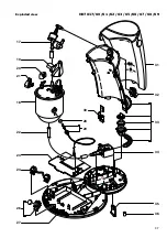
HD7817/60 /61 /62 /63 /65 /66 /67 /68 /69

2-7

Disassembly information

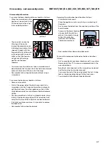
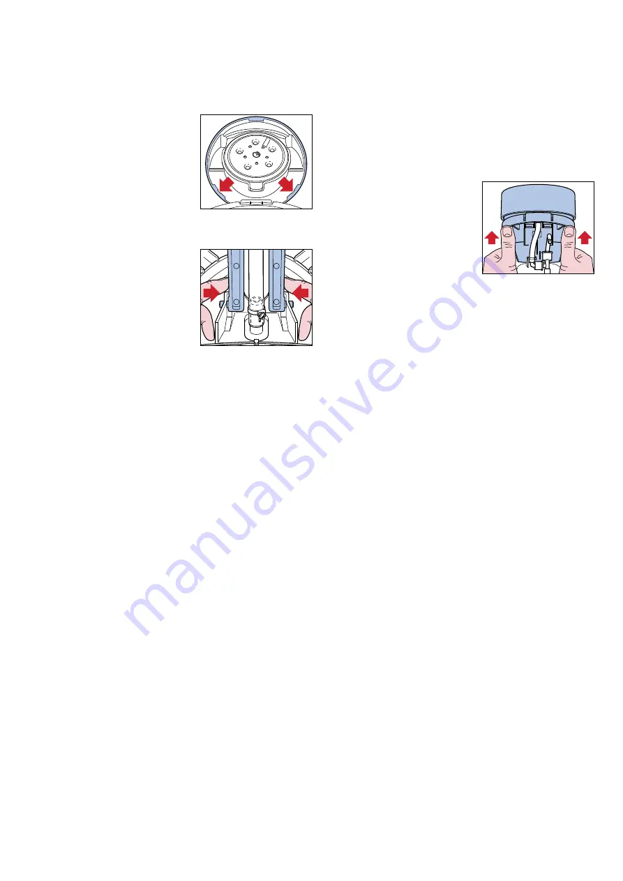
To remove the brew chamber lid cover handle as follows: 


Place the screwdriver on the 

positions (see picture 1) and 

lift the cover over the snap 

locks on both positions.


The cover lid can now be 

lifted up a little and to 

remove the complete cover 

including lever and push rod 

squeeze strongly with two 

fingers both legs of the push 

rod (see picture 2) to each 

other, so that the two pins 

will get out of the hinge 

position on the brew 

chamber.


To remove lever from lid cover, take a screwdriver and 

bend carefully the two lips/ribs in the lid cover outwards 

and push the lever with force out of the hinge.


Reassemble follow steps backwards, without using a 

screwdriver.

To remove the back cover handle as follows:


Remove valve outlet.


Start at the upper side of the back cover and stick a 

screwdriver into the 2 snap locks positions and gently 

pull the back cover from the appliance so that a little 

chink between back cover and brew chamber becomes 

visible.


Put the screwdriver in to the 4 rectangular holes (snap 

locks) at the back and gently pull the screwdriver such 

away that the lips of the snap locks are bent outwards.


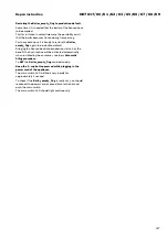
If all clicks positions are loose, it is possible to remove 

the back cover.


Reassemble follow steps backwards.

picture 1

picture 2

Removing Brew chamber head handle as follows:


Disassemble back cover!


Place the appliance such a way that you are looking at 

the boiler.


First remove the boiler from the snap lock position of the 

brew chamber.


To remove the brew chamber, 

use your both thumbs (see 

picture 3) and push strongly 

with a little distortion 

(rotation) until the brew 

chamber comes loose.


Reassemble follow above steps backwards.

To reach the components placed on the base handle as 

follows:


First remove back cover, brew chamber and 3-way valve.


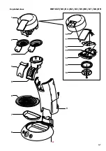
Remove both Torx T15 screws see exploded view in the 

near of position 

A

.


Bend the 2 click snap locks with a screwdriver (see base), 

and the housing can now be removed.


To remove the rest of the housing unlock the last 4 snap 

locks at the base and gently pull of the front cover.


To reassemble follow above steps backwards.

picture 3

Disassembly- and reassembly advice

Summary of Contents for HD7817/60

Page 1: ...ion This product meets the requirements regarding interference suppression on radio and TV After the product has been repaired it should function properly and has to meet the safety standards as officially laid down at this moment Technical information Voltage 230 V Frequency 50 Hz Power consumption 1450 W Standby power consumption 0 5 W Stand by time 30 min Functions Brew stop Contents reservoir ...

Page 2: ...hamber becomes visible Put the screwdriver in to the 4 rectangular holes snap locks at the back and gently pull the screwdriver such away that the lips of the snap locks are bent outwards If all clicks positions are loose it is possible to remove the back cover Reassemble follow steps backwards picture 1 picture 2 Removing Brew chamber head handle as follows Disassemble back cover Place the applia...

Page 3: ...L Max water cc mL France version 104 120 General Europe version 125 141 7 Unplug the appliance from the mains 8 Press the 1 and 2 cup button simultaneously and plug the mains on 9 When above step succeeded the led will turn on continuously 10 Depending if the volume has to de or increase you have to push the one or two cup button Every time you push the 1 or 2 cup button the LED will turn off for ...

Page 4: ...inging the Senseo back into production status has the benefit the flush routine will be activated automatically when installed by the consumer see topic Automatic filling procedure To SET the Boiler_empty_flag can be done by Keep the 1 cup button pressed while plugging in the power cord of the appliance The main switch LED will blink very rapidly for approximately 1 second To check if the Boiler_e...

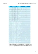
Page 5: ... 259 59541 3 way valve 18 4222 259 52091 Boiler assy V7 0 230 V 19 4222 247 61940 TCO cap 20 4222 247 43690 Boiler pin cap 21 4222 247 72551 Suspension bracket 22 4222 247 06511 Pressure hose 23 4222 259 61702 PCB assy 1 24 4222 259 62221 Button frame printed Black 26 4222 259 63421 On off button printed 27 4222 247 72932 Base plate Black 28 4222 247 05130 O ring NTC 29 4222 259 39372 NTC assy 30 ...

Page 6: ...HD7817 60 61 62 63 65 66 67 68 69 6 7 A 15 12 10 14 13 11 16 6 2 1 4 3 7 8 5 9 Exploded view ...

Page 7: ...HD7817 60 61 62 63 65 66 67 68 69 7 7 36 35 34 31 32 17 18 22 24 23 19 20 30 21 26 27 29 28 33 A Exploded view ...

Reviews: