Top Case Assemblies
4
-
34
Removal and Replacement
Control PCA
The steps below describe how to remove and replace the Control PCA. The
Control PCA contains the unit’s operating software, including the data for the
voice prompts. All Control PCAs are American English, part number
M3500-68100. Installing a new Control PCA requires the use of the
Language Support Tool to set the Control PCA to the corrrect language. See
Table 5-2 on page 5-7 for part numbers.
Removal
1. If possible, save the customer’s configuration onto a Data Card (or print
the configuration) so the configuration can be restored after the repair is
complete.
2. Disconnect the Control PCA from the rest of the unit and from the display
as described in "Disconnecting the Control PCA" on page 4-31.
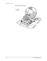
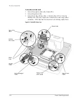
3. Remove the 8 screws around edges of the Control PCA - not the screws in
the metal shield. See Figure 4-20 on page 4-35.
4. Remove the 1 screw near the center of the PCA. Be careful not to damage
any nearby components or traces. See Figure 4-20 on page 4-35.
5. Slide the Control PCA toward the rear while lifting it off the metal shield
plate. This will help the Eject button clear its hole in the black plastic
shield surrounding the Data Card receptacle. If the black plastic shield is
damaged, remove it; otherwise leave it in place.
6. Leave the lithium backup battery in place when returning the PCA for
repair. This will help preserve information for factory troubleshooting.
Summary of Contents for Heartstart XLT
Page 1: ...H E A R T S TA R T X LT S e r v i c e M a n u a l M 3 5 0 0 B M 5 5 0 0 B ...
Page 2: ......
Page 3: ...Service Manual M3500B HeartStart XLT M5500B Heartstart 4000 Defibrillator Monitor ...
Page 6: ......
Page 16: ......
Page 20: ......
Page 52: ......
Page 216: ......
Page 223: ......
Page 224: ...M3500 90900 Printed in USA February 2003 Second Edition M3500 90900 2 ...


