M3500B/M5500B Service Manual
4
-
47
Top Case Assemblies
4
Replacement
1. Prepare the case as follows:
a.
Clean off all adhesive residue from the case and manual door rails by
rubbing the dry surface with your finger and ’rolling up’ the adhesive.
Lightly scoring the adhesive with a rounded tool will aid removal.
Solvents are ineffective, as is scraping with a sharp tool.
NOTE
The adhesive used is very difficult to remove. Take your time and do a thor-
ough job to ensure a correct seal with the new switches and overlay.
b.
Clean surfaces thoroughly with isopropyl alcohol (an alcohol wipe is
fine). Allow to dry completely.
2. Install the new membrane switches as follows:
a.
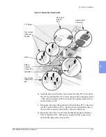
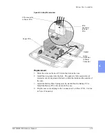
Feed the 2 flex circuits down through the slot in the case as shown in
Figure 4-28. Slide the smaller one in first, then the larger one. Feed
them around the side of the Interface PCA nearest their connectors.
b.
Peel the backing material off the new switches. Handle very carefully
and touch the adhesive as little as possible.
c.
Starting with the top edge, align the switches very carefully in their
recess in the case and roll them down slowly into place. Be careful
not to kink the flex circuit tails as you slide them into their slot under
the switches.
d.
Press firmly all over, especially the edges, to adhere the new switches
into place and seal the case opening.
Figure 4-28 Installing the Membrane Switches
Membrane
Switches
Flex Circuits to
Interface PCA
Summary of Contents for Heartstart XLT
Page 1: ...H E A R T S TA R T X LT S e r v i c e M a n u a l M 3 5 0 0 B M 5 5 0 0 B ...
Page 2: ......
Page 3: ...Service Manual M3500B HeartStart XLT M5500B Heartstart 4000 Defibrillator Monitor ...
Page 6: ......
Page 16: ......
Page 20: ......
Page 52: ......
Page 216: ......
Page 223: ......
Page 224: ...M3500 90900 Printed in USA February 2003 Second Edition M3500 90900 2 ...


