M3500B/M5500B Service Manual
4
-
31
Top Case Assemblies
4
Disconnecting the Control PCA
These instructions cover how to disconnect the Control PCA - from the rest of
the unit, and from the display. These procedures are often needed when
removing and replacing other assemblies.
From the Rest of the Unit
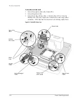
Disconnect the 4 cables that connect the Control PCA to the rest of the unit.
See Figure 4-18 on page 4-32.
1. Disconnect the two large ribbon cables on the left side of the Control PCA
(1 connects to the Power PCA, 1 to the Interface PCA). Both of these
require removal of metal bails (retainer clips) over their tops. Take care to
not bend the bails.
2. Disconnect the small ribbon cable at the rear of the PCA (connects to the
printer). This requires releasing latches on the ends of connector - push
the latches out and down to release them.
3. Disconnect the small 2-wire speaker connector at the edge of the PCA.
This connector has a latch on the top - push down on the latch to release it
and wiggle the connector side to side to pull it out.
From the Display
Also referring to Figure 4-18 on page 4-32, disconnect the 3 cables that con-
nect the Control PCA to the Display.
1. Disconnect the flex circuit on the right side of the Control PCA (the Dis-
play Data Cable). Pull out the latches on the ends of connector to release
it before pulling on the flex.
2. Disconnect the white connector next to it (the display thermistor cable).
This connector has a tiny latch - using a small flat blade screwdriver, push
down in the slot that runs across the receptacle and push the plug out of
the receptacle.
3. Disconnect the small 2-wire connector (the display backlight cable) on
the edge of the Control PCA nearest the handle, next to the speaker con-
nector. It also has a tiny latch - push in the center slot with small flat
bladed screwdriver using the corner of the blade, and push connector out
of receptacle.
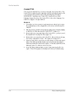
Reconnecting the Control PCA
The following steps describe how to reconnect the Control PCA - to the dis-
play, and to the rest of the unit. These procedures are often needed when
removing and replacing other assemblies.
To the Display
1. Connect the display backlight cable to the Control PCA.
2. Connect the display thermistor cable.
3. Insert the display data cable into its connector and latch into place.
Summary of Contents for Heartstart XLT
Page 1: ...H E A R T S TA R T X LT S e r v i c e M a n u a l M 3 5 0 0 B M 5 5 0 0 B ...
Page 2: ......
Page 3: ...Service Manual M3500B HeartStart XLT M5500B Heartstart 4000 Defibrillator Monitor ...
Page 6: ......
Page 16: ......
Page 20: ......
Page 52: ......
Page 216: ......
Page 223: ......
Page 224: ...M3500 90900 Printed in USA February 2003 Second Edition M3500 90900 2 ...


