3-3
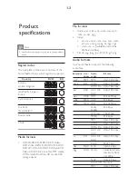
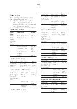
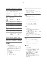
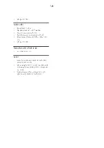
Mechanical and Dismantling Instructions
Dismantling Instruction
Detailed information please refer to the model set.
Step
6
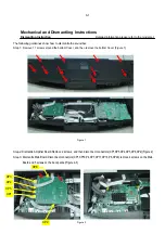
Dismantle loader. Remove 4 screws, disconnect connectors(P4,XP7,XP17,XP16),and then remove the loader. (Figure 6)
Figure
6
Step
8
:
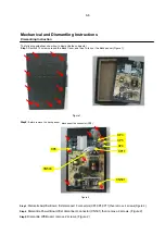
Dismantle Power Board. Remove 2 screws, disconnect connectors(CN504,CN501),and then remove the Power Board. (Figure 7)
Step
9
:
Dismantle IN Board. Disconnect connectors(XP1,XS609),remove 1 screw,and then remove the IN Board. (Figure 7)
Figure
7
Step
7
:
Dismantle Key Board. Remove 5 screws, disconnect connector(XS1),and then remove the Key Board. (Figure 6)
XS1
XP1
XS609
CN504
CN503
P4
P4
XP7
XP17
XP16
Summary of Contents for HTB5150D/12
Page 62: ...Key Board Print layout bottom side for HTB5150D 12 Soundbar 7 26 7 26 ...
Page 63: ...Power Board Print layout bottom side for HTB5150D 12 Soundbar 7 27 7 27 ...
Page 64: ...IN Board Print layout top side for HTB5150D 12 Soundbar 7 28 7 28 ...
Page 65: ...IN Board Print layout bottom side for HTB5150D 12 Soundbar 7 29 7 29 ...
Page 66: ...FV Board Print layout top side for HTB5150D 12 Soundbar 7 30 7 30 ...
Page 67: ...FV Board Print layout bottom side for HTB5150D 12 Soundbar 7 31 7 31 ...
Page 68: ...Amplifier Board Print layout top side for HTB5150D 12 Soundbar 7 32 7 32 ...
Page 69: ...Amplifier Board Print layout bottom side for HTB5150D 12 Soundbar 7 33 7 33 ...
Page 70: ...Main Board Print layout top side for HTB5150D 12 Soundbar 7 34 7 34 ...
Page 71: ...Main Board Print layout bottom side for HTB5150D 12 Soundbar 7 35 7 35 ...
Page 72: ...Power Board Print layout bottom side for HTB5150D 12 Subwoofer 7 36 7 36 ...
Page 79: ...Exploded View of HTB5150D 12 Soundbar 10 1 10 1 ...
Page 80: ...Exploded View Of HTB5150D 12 Subwoofer 10 2 10 2 ...

