background image

EN 8

3139 785 31460

3. 

Directions For Use

The following except of the Quick Use Guide serves as an introduction to the set.

The Complete Direction for the Use can be downloaded in dif

ferent languages from the internet site of Philips Customer care Cen

ter: 

www

.p4c.philips.com

Quick Star t Guide

HTS 5310S

What’s in the Box

Home Theatre System

Need help?

User Manual

For more product information refer to the user
manual of the home theatre system.

Online

Go to www.philips.com/support

2005 © Koninklijie Philips N.V.
All rights reserved.
12 NC 31 39 115 16351
www.philips.com

Troubleshooting

For more troubleshooting tips, see the user manual.

Problem

Tip

No power

• Check if the AC power cord is properly connected.
• Press the STANDBY-ON on the front of the DVD system to turn on the power.

No picture

• Press DISC on remote control.
• Check connection to TV and ensure the plugs are firmly in place.

No sound or

• Adjust the volume.

distorted sound

• Check the speaker connections and settings.
• Check audio connections and press SOURCE button to select the correct input source.

Remote control

• Check that the batteries are loaded correctly or replace the batteries with new ones.

does not work

• Select the source (DISC or TUNER, for example) before pressing the function button.
• Reduce the distance between the remote control and the system.
• Point the remote control directly toward the IR sensor.

DVD system

Scart cable

(black plug)

Rear speakers

(left & right)

Listen to Radio

1

Press

TUNER

.

2

Press and hold

PLAY

until ‘START’ appears.

Tip

This feature is only available

for first time setup, refer to user
manual if you wish to program
radio stations again or for manual
programming.

3

Once completed you can use

NEXT

or

PREVIOUS

to select a radio station.

Front display

Remote control

and 2 batteries

Quick start guide

Centre speaker

Subwoofer

Play DVD

1

Press

OPEN/CLOSE

on the front of

the DVD system to open the disc tray.

2

Place DVD in tray with the label facing up.

3

Press

OPEN/CLOSE

again.

4

Press

UP

, DOWN

,

RIGHT

or

LEFT

to scroll through the options in

the DVD menu.

5

Press

PLAY

on the option you want.

6

To stop press

STOP

.

Tip

Press

PLAY

to resume from where

you stopped or press

STOP

and

PLAY

to start from the beginning of the title.

7

Press

DISC MENU

to go back to the

DVD menu.

DVD Player (front)

Front speakers

(left & right)

Experience Surround Sound

1

Press

SURR

to switch between Stereo and

Multi-channel.

2

Press

SOUND

for either Concert, Drama,

Action or Sci-fi preset digital sound effects.

AM/MW

loop antenna

FM wire antenna

User manual

Connect

Setup

Enjoy

Enjoy

3.

Directions For Use

Summary of Contents for HTS 3610

Page 1: ... Board Circuit Diagram Part 2 22 Mono Board Circuit Diagram Part 3 23 Mono Board Circuit Diagram Part 4 24 Mono Board Circuit Diagram Part 5 25 Mono Board Circuit Diagram Part 6 26 Mono Board Circuit Diagram Part 7 27 Mono Board Circuit Diagram Part 8 28 Mono Board Circuit Diagram Part 9 29 Layout Mono Board Top View 30 Layout Mono Board Bottom View 31 Copyright 2005 Philips Consumer Electronics B...

Page 2: ...s and Connection Facilities LOCATION OF PC BOARDS HTS3610 Video Yellow Cinch Component Video Y Pb Pr P scan SCART CVBS RGB Digital In Coaxial TV In Left Right Auxiliary Left Right Line out Audio VERSION VARIATIONS HTS3610 12 HTS3610 51 x x x x x x ...

Page 3: ... 55 93 Grid 9kHz for 12 05 51 98 93 55 10kHz for 98 55 93 IF frequency 450kHz 1kHz Aerial input Frame aerial Sensitivity at 26dB S N 4 0mV M Selectivity at 18kHz bandwidth 20dB IF rejection 45dB Image rejection 28dB Distortion at RF 50mV m 80 5 1 3 AMPLIFIER Output power Front 100W RMS channel Rear 75W RMS channel Center 100W RMS Subwoofer 150W RMS Frequency response 0 5dB 20Hz 20kHz Hum Volume Mi...

Page 4: ... the source DISC or TUNER for example before pressing the function button Reduce the distance between the remote control and the system Point the remote control directly toward the IR sensor DVD system Scart cable black plug Rear speakers left right Listen to Radio 1 Press TUNER 2 Press and hold PLAY until START appears Tip This feature is only available for first time setup refer to user manual i...

Page 5: ...eatedly press the Channel Down button until you see the General Setup Page This is the correct viewing channel for the home theatre system Tip In some TVs to find the correct viewing channel you can keep pressing the AV or the SELECT buttons If still unable to find the correct viewing channel check the connections again or check your TV s user manual 6 Press SETUP to finish Tip To make changes to ...

Page 6: ... hooks on the bottom side pos 161 4 Loosen 4 screws E see Figure 3 4 to remove the PSU Module 4 Dismantling Instructions 4 1 Dismantling of the DVD Loader 1 The tray can be manually open by inserting a minus screw drive and push the lever in the direction as shown in Figure 3 1 to unlock the tray before sliding it out Figure 4 1 2 Slide out the tray and remove the Cover Tray pos 110 as shown in Fi...

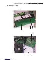
Page 7: ...EN 11 3139 785 31460 4 Dismantling Instructions Service Positions 4 3 Service Positions Mono Board Thick Insulation Sheet Front Board Thick Insulation Sheet PSU Board DVD Loader ...

Page 8: ... Software version number of BEA counting up from 01 to 99 yy refers to Software version number of Front uP counting up from 01 to 99 5 1 Display Test Purpose This test is used to check the driving circuits the display and whether there are any short circuits open circuits or any other defects Player Following display patterns are used to test the display and its connections to μP Pattern 1 Default...

Page 9: ...rchive into the root directory of the new CD project 4 Burn the data onto a blank CDR or CDRW Note ISO9660 is mandatory UDF discs are not supported The final CDROM must not contain any other data except the file from the zip archive 5 1 4 Procedure to upgrade the firmware 1 Power up the set and open tray 2 Insert the prepared Upgrade CDROM and close the tray 3 The set will display LOAD MULTICH UPG...

Page 10: ...EN 14 3139 785 31460 6 FTD Display Pin Connection 6 FTD Display Pin Connection ...

Page 11: ... 24 FOC 1101 GND_LD 1 DVD LD 2 NC 3 HFM 4 MD 5 CD_LD 6 VD_DVD 7 VD_CD 8 NC 9 E 10 VCC 11 VREF 12 GND 13 F 14 B 15 A 16 RF 17 CD_DVD SW 18 C 19 D 20 TRACK 21 TRACK 22 FOC 23 FOC 24 7203 M29W160ET70 FLASH 5M L_V33 L_V33 7110 MM1646XH Motor Drivers LOAD 1 LOAD 2 TROUT 3 GND 4 TRIN 5 1105 7200 IM24C16 RDW6 NVRAM 1109 1401 5130 27MHZ 7202 CS8415A Digital Audio Interface receiver 1502 SP 1 SP 2 LIMIT 3 ...

Page 12: ... Front 313911101901 MIS 09 340 09 OE 5VL 12VL GND 5V EV 24V VSTB VSTA VSCK GND 41K RC6 STBY NC NC 1 9 1 5 9P EH BOARD INTO MONO Front MIC 3139 113 35771 3139 113 35761 FR1 2 layer 2P stand by switch 313911104521 MIS 04 480 04 OE 8701 313911103311 MIS 02 220 02 OE 313911103541 MIS 05 18 3139 243 31471 141X382 FR4 2 layer 12VA MIC GND 12A 4P EH TO mono MIC Port s TU_SCL TU_SDA TU_SD TU_L TU_Stereo T...

Page 13: ...7 K 4 BC847B 7703 1716 SKQNAB p 0 0 1 8 0 7 2 47p 2709 7 0 7 2 0 u 1 4704 BAS316 6718 4703 3732 1M0 BAS316 6703 1K0 MGND MGND 3708 6 1 3 S A B 6 1 7 6 1 2 3 4 5 MGND 1703 WH05D 1 0 3 7 3 7 K 4 F724 330R 3735 2 1 7 2 p 0 1 MGND 6 1 3 S A B 9 0 7 6 2702 470n 7707 BC847B 1715 SKQNAB F712 F705 3720 4K7 6 1 3 S A B 5 1 7 6 R 0 3 3 6 3 7 3 1K2 3 3 5 4 4 3 1 5 3701 19 20 21 22 23 9 1 2 3 4 4 1 28 29 30 3...

Page 14: ...140 DVDD3_5 141 RCS 142 143 BA0 DVSS_7 144 145 BA1 RA10 146 132 RD10 133 RD9 134 DVSS_6 RD8 135 DQS1 136 DQM1 137 138 RWE CAS 139 0 D R 6 2 1 5 1 D R 7 2 1 4 _ 3 D D V D 4 1 D R 8 2 1 RD13 129 13 SB RD12 130 131 RD11 5 D R 9 1 1 5 _ S S V D 12 SA 0 2 1 4 D R 1 2 1 3 D R 3 _ 8 1 D D V D 2 2 1 3 2 1 2 D R 1 D R 4 2 1 5 2 1 T S R P 1 1 1 R I 0 T N I 2 1 1 0 M Q D 3 1 1 0 S Q D 4 1 1 7 D R 5 1 1 6 1 1...

Page 15: ...5 8 4 M24C16 RDW6 7200 3240 10K D 9 5 2 2 p 2 2 3229 D 22R n 7 4 3 7 2 2 10R 4 5 3211 4 5200 4 5 2257 3214 4 10R 100n 16V 47u 2258 2256 100n 10K 3200 100n 2268 10R 3214 1 1 8 D 1 4 4 5 6 2 1 6 4 2 5 16 40 18 1 4 1 7 2 3 9 3 4 9 4 8 2 7 8 10 11 13 42 44 39 15 36 37 38 19 2 4 45 47 48 50 51 53 5 26 29 30 31 32 33 34 20 21 17 7201 23 24 22 35 25 10R 2 7 IS42S16400A F DRAM 1M X 16 X 4 3210 2 10K 3204 ...

Page 16: ... 3 2 1 3 2 5 1 3 2 V 5 3 u 0 7 4 5K6 3311 9 1 3 3 K 0 1 6 V 5 C 4 8 3 X Z B 0 0 3 6 6 1 3 2 V 5 3 u 0 7 4 2302 100p 5K6 3301 4309 3305 1K0 5K6 1305 3315 0 K 1 1 4 3 3 602K7 4K7 3347 2 1K0 3307 7305 BC847B 1 3 T313 0 4 3 3 0 K 1 BC847B 7308 1 3 2 4K7 3343 V 6 1 u 2 2 6 2 3 2 BAS316 1K0 3317 6305 BAS316 6304 T304 T302 T303 T301 T300 1u0 2331 2334 10u 100K 3325 F306 4305 4304 100p K 0 1 2309 7 3 3 3 ...

Page 17: ...2 24 VSSD 17 VSSP1 VSSP2 20 I B A T S 8 1 19 SUB VSSD VDDA1 10 VDDA2 3 VDDP1 14 VDDP2 23 VSSA1 12 1 4 2 N I 6 E D O M C S O 7 1 T U O 6 1 2 T U O 1 2 T O R P 3 1 1 D N G S 1 1 2 D N G S 2 R O S N E S P M E T T O R P T N E R R U C D O M D O M M W P M W P R E G A N A M P N I P N I E G A T S 0 0 3 7 5 1 1 T O O B 2 T O O B 2 2 1 N I 8 1 N I 9 2 N I 5 W O L W O L H G I H H G I H R E V I R D R E V I R ...

Page 18: ... 3501 F517 GND_A F502 1 4 8 GND_A LM833D 7500 1 3 2 7 4 5 3 8 K 6 7 0 5 2 4K7 3534 F525 p 8 6 12AM GND_A GND_A 12AM GND_A 10K 3500 7502 BC547B p 8 6 K 0 1 6 4 5 3 8 1 5 2 F516 V 9 _ U T 8 K 6 8 2 5 3 D F505 2506 1u0 4515 3502 10K 3 1 2 560R 3529 1501 LPR6520 J920G D GND_A GND_A GND_A GND_A D D GND_tu GND_A GND_A 9 1 5 2 p 0 0 1 3 2 5 3 K 0 0 1 2516 1u0 12AM GND_A F507 GND_A 6 2 5 3 K 2 2 F513 GND_...

Page 19: ... 9 7 6 2 n 0 2 2 2K2 3620 12K 12AM 3624 GND_A 3V3_A 100p 2693 2636 1 8 4 100n LM833D 7616 1 3 2 p 0 2 2 3 6 6 2 GND_A 3646 12AM DAC_RS 3K3 12AM 2u2 2646 4602 p 0 2 2 7 9 6 2 DAC_L 100n GND_A 5VA 2694 GND_A 3611 4K7 A _ D N G 12AM 8 9 6 2 p 0 2 2 2 3 6 7 8 4 5 1 GND_A 7619 MC78L05ACD R2 47K 3649 GND_A 2u2 GND_A 2655 2u2 2658 p 0 2 2 3 2 6 2 3665 5K1 2684 100p 3619 4K7 10K 3654 GND_A 3656 47K p 0 2 ...

Page 20: ...01 1u0 GND_A 2715 V 5 2 u 0 1 6 2 7 2 1K0 3765 1K0 3778 0 n 1 n 0 0 1 5 3 7 2 6 0 7 2 7 1 7 2 V 6 1 u 0 2 2 GND_A GND_A 2u2 2722 2u2 2703 2K2 GND_A 3706 T256 T257 T713 T714 T711 T712 T710 T709 T708 2732 100n 3K3 3V3 GND_A 3704 6720 BAS316 GND_A GND_A 1u0 2714 3756 1K0 470R 3792 4K7 3787 12AM 3722 5K1 2721 150p 3785 470R 2718 100u 16V GND_A 7718 BC847B 2 6 1 GND_A BC857BS 7721 1 6725 BAS316 7 6 7 3...

Page 21: ...8 3 K 2 2 D K 2 2 0 1 8 3 T802 5V D 12VL T817 3849 220R BC857B 7814 4816 3834 R 0 2 2 3 4 8 3 R 2 8 2850 2 u 2 D 8 T809 2 3 4 5 GND MSP 801V1 02 01 B NI FE LF 1802 C 6 MSP 801V1 02 01 B NI FE LF 1802 A 1 1802 B MSP 801V1 02 01 B NI FE LF 7 220p 2815 4 1 8 4 T812 5V 2818 220p 4819 D F801 2 2 8 3 R 5 7 K 0 1 8 1 8 3 12K 3819 3 1 8 4 4820 D D 5V 4 4 8 3 R 0 2 2 F803 T800 7813 BC857B 7 5D 4 6 8 12 13 ...

Page 22: ...6 B3 2918 C3 2920 B2 2921 B1 F911 F906 F903 F907 F912 F910 F909 F905 1901 1 2 F913 2 0 9 3 B2B EH A 6 R 5 5 K 1 7 0 9 3 R 0 7 4 3 0 9 3 T902 T903 T900 T901 D GND_A 3V3 D D 5VL F901 12A 12A D 3V3 0 2 9 2 D p 0 0 1 8 1 9 2 p 0 0 1 D 2914 100p D D 100p 2913 2 1 9 2 p 0 0 1 D D 100p 2911 7900 3V3 BC327 25 BZX384 C4V7 2 0 9 2 n 0 1 4 5 6 7 8 9 6900 B12B EH A 1 10 11 12 2 3 R 8 6 1900 8 0 9 3 u 0 1 0 0 ...

Page 23: ...EN 32 3139 785 31460 8 Circuit Diagram and PWB Layout PSU Circuit Diagram For information only PSU 04 01 Circuit Diagram 1702 04 11 01 pdf_052005 ...

Page 24: ...5614 CER2 0805 X7R 100V 220P PM10 R 2416 2238 600 15614 CER2 0805 X7R 100V 220P PM10 R 2420 2238 600 15614 CER2 0805 X7R 100V 220P PM10 R 2427 2020 021 91431 ELCAP YXA 100V S 22U PM20 2435 2238 600 15614 CER2 0805 X7R 100V 220P PM10 R 2438 2238 600 15614 CER2 0805 X7R 100V 220P PM10 R 2439 2238 600 15614 CER2 0805 X7R 100V 220P PM10 R 2440 4822 126 13473 220NF80 20 50V 2443 2238 600 15614 CER2 080...

Page 25: ...SM TDA8922BTH N2 PHSE R 7502 4822 130 40959 BC547B 7503 5322 209 11102 HEF4052BT 7504 9340 425 20115 TRA SIG SM BC847BS PHSE R 7613 4822 209 30095 LM833D 7615 9322 215 93668 IC SM CS42406 CQZ CILO R 7616 4822 209 30095 LM833D 7619 4822 209 33411 MC78L05ACD 7621 4822 209 30095 LM833D 7720 5322 130 60159 BC846B 7721 9340 425 10115 TRA SIG SM BC857BS PHSE R 7723 9340 425 30115 TRA SIG SM BC847BPN PHS...

Page 26: ...0V 220P PM10 R 2416 2238 600 15614 CER2 0805 X7R 100V 220P PM10 R 2420 2238 600 15614 CER2 0805 X7R 100V 220P PM10 R 2427 2020 021 91431 ELCAP YXA 100V S 22U PM20 2435 2238 600 15614 CER2 0805 X7R 100V 220P PM10 R 2438 2238 600 15614 CER2 0805 X7R 100V 220P PM10 R 2439 2238 600 15614 CER2 0805 X7R 100V 220P PM10 R 2440 4822 126 13473 220NF80 20 50V 2443 2238 600 15614 CER2 0805 X7R 100V 220P PM10 ...

Page 27: ...SM TDA8922BTH N2 PHSE R 7502 4822 130 40959 BC547B 7503 5322 209 11102 HEF4052BT 7504 9340 425 20115 TRA SIG SM BC847BS PHSE R 7613 4822 209 30095 LM833D 7615 9322 215 93668 IC SM CS42406 CQZ CILO R 7616 4822 209 30095 LM833D 7619 4822 209 33411 MC78L05ACD 7621 4822 209 30095 LM833D 7720 5322 130 60159 BC846B 7721 9340 425 10115 TRA SIG SM BC857BS PHSE R 7723 9340 425 30115 TRA SIG SM BC847BPN PHS...

Reviews: