3-3
Mechanical and Dismantling Instructions
Dismantling Instruction
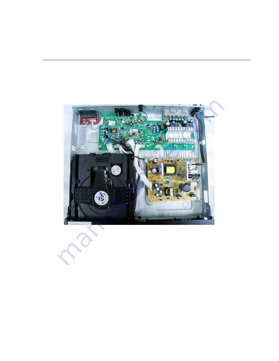
Figure 6
Detailed information please refer to the model set.
Step6
Step7
Step8: Dismantl
e
AV Board, first disconnect 1 connector(XP11),and then remove
: Dismantle Main Board, first disconnect
1
connector (XP36), and then remove
7
screws. (Figure
5/
6)
: Dismantl
e
Power Board, disconnect the connector
s
X
P
3 and XS703 ,then remove
5
screws.(Figure
5/
6)
(Figure
5/
6)
3 screws
Summary of Contents for HTS2511/05
Page 20: ...AUDIO L R R L AUDIO IN L R AUDIO OUT VIDEO AUDIO L R VIDEO OUT VIDEO IN 2 4 ...
Page 24: ...2 1 2 8 ...
Page 52: ...7 12 7 12 Front Control Board Print layout Bottom Side ...
Page 53: ...7 13 7 13 AV Board Print layout Bottom Side ...
Page 54: ...7 14 7 14 Power Supply Print layout Bottom Side ...
Page 55: ...7 15 7 15 Main Board Print layout Top Side ...
Page 56: ...7 16 7 16 Main Board Print layout Bottom Side ...
Page 57: ...Exploded View for HTS2511 12 05 8 1 ...


