


A
A
B
B
C
C
D
D
E
E
1
1
2
2
3
3
4
4
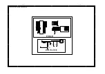
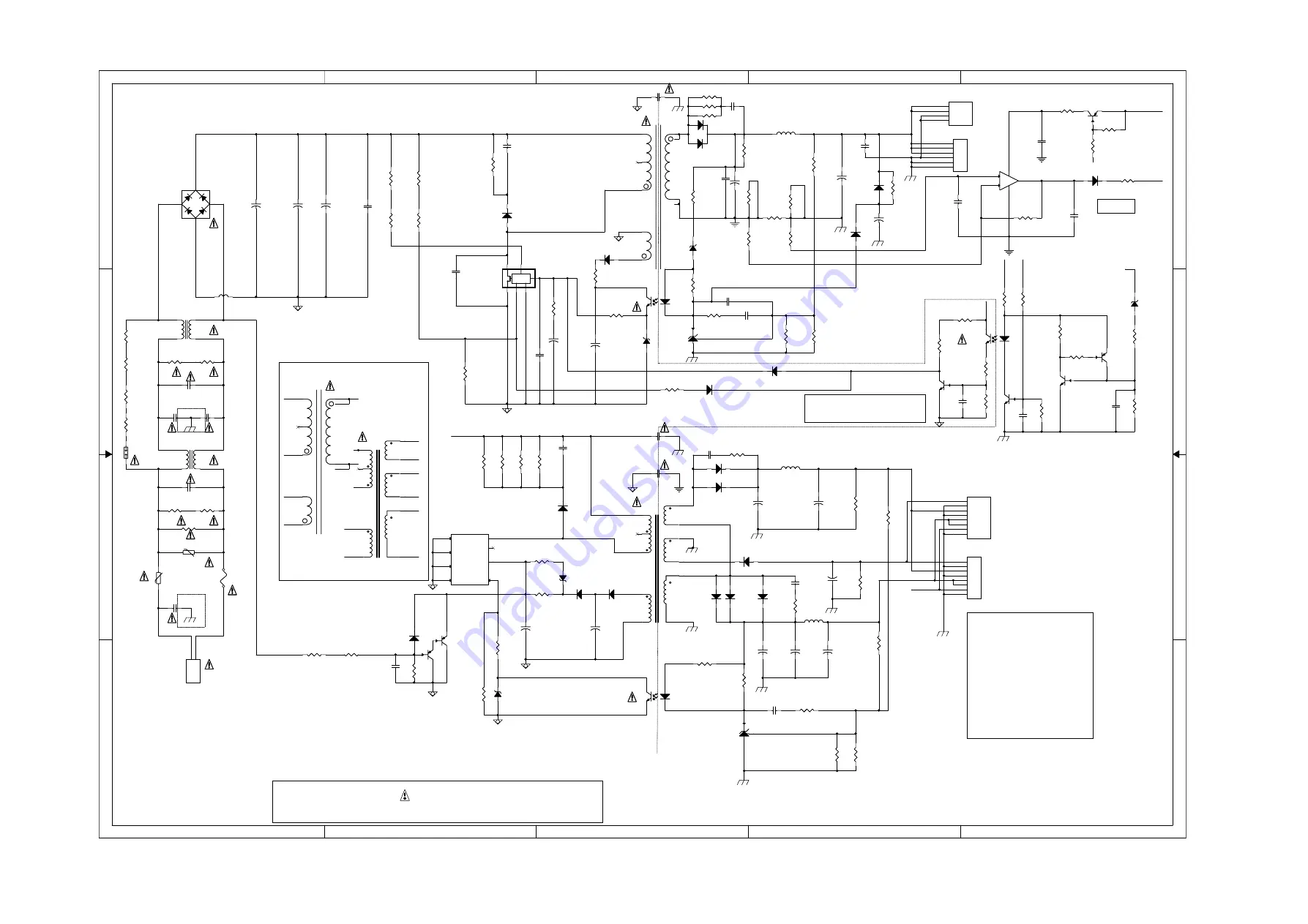
PLEASE USE THE PARTS HAVING THE DESIGNATED PARTS NUMBER WITHOUT FAIL.
* CAUTION :
THE PARTS MARKED WITH ARE IMPORTANT PARTS ON THE SAFETY.
Remote on/off
Standby mode: Q561, D561 OFF; D562 ON
On mode: Q561, D561 ON; D562 OFF
1:-24V
2:GND
3:+12V
4:GND
5:M+5V
6:M+5V
7:P_on/off
8:GND
1:+33V
2:+33V
3:+33V
4:GND
5:GND
6:GND
Alternative
Alternative Alternative
Alternative
Alternative
Alternative
Alternative Alternative Alternative
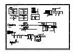
BD mode
T501:EF25
U501:TNY179P
+12V:
D511:HER203
C503:1000pF/1kV
R514:22/1206
CE506:1000uF/16V
CE507:470uF/16V
+5V:
D510:SR360
CE509:2200uF/16V
CE510:1000uF/16V
CE511:1000uF/16V
DVD mode
T501:EEL19
U501:TNY177P
+12V:
D511:FR107
C503:NC
R514:NC
CE506:470uF/25V
CE507:220uF/25V
+5V:
D510:NC
CE509:1000uF/16V
CE510:NC
CE511:470uF/16V
Alternative
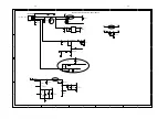
OPP Circuit
Alternative
Alternative
Alternative
Alternative
Alternative
Alternative Alternative
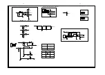
+12V
T501N
HV
T501G
T501P12
T501D
OPP
M+5
V
T531G
T531D
T501N
T501P24
T531F
T531P
T531N
+10V
HV
OP
PCON
+33V
T501F
OP
M+5V
OPP
HV
HV
T531D
T531G
T531F
T531P
T501F
T501G
+10V
T501N
T501P12
T501P5
T501N
T501P24
T501P5
T501D
T531N
T501P5
+33V
M+5V
PCON
P
P
P
P
R502C
NC
R502C
NC
D535
1N4148
D535
1N4148
R549
0
R549
0
+
47uF/35V
CE531
+
47uF/35V
CE531
C573
0.1uF/50V/X7R
C573
0.1uF/50V/X7R
ZD532
BZX79C12
ZD532
BZX79C12
R517
NC
R517
NC
R570
100
R570
100
R520
NC
R520
NC
C532
0.1uF/50V/X7R
C532
0.1uF/50V/X7R
R511 470
R511 470
R576
1K
R576
1K
R505B
150K
R505B
150K
+
10uF/50V
CE532
+
10uF/50V
CE532
R532
NC
R532
NC
LIF502
6.6mH
LIF502
6.6mH
+
2200uF/16V
CE509
+
2200uF/16V
CE509
Q563
NPN_3DG3904M
Q563
NPN_3DG3904M
R502A
NC
R502A
NC
T5011
EEL19
T5011
EEL19
9
1
3
5
10
8
2
1
6
7
8
R523
100
R523
100
R536
2M/5%
R536
2M/5%
RV501
VDR/560V
RV501
VDR/560V
CN501
2PIN/7.92mm
CN501
2PIN/7.92mm
1
1
2
2
C
S
D
V
F
CONTROL
X
U531
TOP258EN
C
S
D
V
F
CONTROL
X
U531
TOP258EN
R540C 22
R540C 22
R545
2.67K/1%
R545
2.67K/1%
R519
2.4K/1%
R519
2.4K/1%
+
10uF/16V
CE505
+
10uF/16V
CE505
CX501
0.33uF/250VAC
CX501
0.33uF/250VAC
R508
22K
R508
22K
+
22uF/50V
CE537
+
22uF/50V
CE537
D511
HER203G/2A/200V
D511
HER203G/2A/200V
R579
1K
R579
1K
Q564
PNP_3CG3906M
Q564
PNP_3CG3906M
R548
0
R548
0
CY501
470pF/250VAC
CY501
470pF/250VAC
D572
1N4148
D572
1N4148
R540A
22
R540A
22
C501
2200pF/1KV
C501
2200pF/1KV
R543
10K
R543
10K
U502
BPC-817B
U502
BPC-817B
1
2
4
3
+
100uF/400V
CE503
+
100uF/400V
CE503
+
1000uF/16V
CE510
+
1000uF/16V
CE510
R563
1K
R563
1K
R518
2.49K/1%
R518
2.49K/1%
R533
NC
R533
NC
R568
1K
R568
1K
R546
NC
R546
NC
T501
EF25
T501
EF25
9
4
3
5
10
8
2
1
6
7
8
C539
0.01uF/400V
C539
0.01uF/400V
Q501
PNP_MMBT8550CLT1
Q501
PNP_MMBT8550CLT1
R544
33.2K/1%
R544
33.2K/1%
+
1000uF/16V
CE506
+
1000uF/16V
CE506
R526
100K
R526
100K
C505
0.1uF/50V/X7R
C505
0.1uF/50V/X7R
L502
3.3uH
L502
3.3uH
R505D
150K
R505D
150K
R547
0
R547
0
LIF501
6.6mH
LIF501
6.6mH
TR501
NTC/3ohm/5A
TR501
NTC/3ohm/5A
R524
150
R524
150
ZD561
BZX79C33
ZD561
BZX79C33
RV504
200V/500A
RV504
200V/500A
R537
2M/5%
R537
2M/5%
-
+
U571A
LM358/SO
-
+
U571A
LM358/SO
3
2
1
8
4
D513
SR3100/3A/100V
D513
SR3100/3A/100V
+
1000uF/16V
CE511
+
1000uF/16V
CE511
L503
3.3uH
L503
3.3uH
C535 0.1uF/50V/X7R
C535 0.1uF/50V/X7R
C534
0.1uF/50V/X7R
C534
0.1uF/50V/X7R
D506
FR107/1A/1000V
D506
FR107/1A/1000V
D507
1N4148
D507
1N4148
D533
10A/200V
D533
10A/200V
1
2
3
R571
10 mR
R571
10 mR
Q562
NPN_MMBT8050CLT1
Q562
NPN_MMBT8050CLT1
CY505
470pF/250VAC
CY505
470pF/250VAC
R516 10K
R516 10K
R502D
NC
R502D
NC
CN502
8PIN/2.5mm/80mm
CN502
8PIN/2.5mm/80mm
1
1
2
2
3
3
4
4
5
5
6
6
7
7
8
8
+
47uF/35V
CE504
+
47uF/35V
CE504
U533
AZ431LBZ
U533
AZ431LBZ
2
1
3
R578
10K
R578
10K
R515
NC
R515
NC
+
47uF/50V
CE508
+
47uF/50V
CE508
D532 FR104/1A/400V
D532 FR104/1A/400V
+
470uF/16V
CE507
+
470uF/16V
CE507
Q502
PNP_MMBT8550CLT1
Q502
PNP_MMBT8550CLT1
CY503
470pF/250VAC
CY503
470pF/250VAC
ZD531
BZX79C8V2
ZD531
BZX79C8V2
R525
150
R525
150
C561
0.1uF/50V/X7R
C561
0.1uF/50V/X7R
FB1
FB90@100MHz
FB1
FB90@100MHz
+
820uF/50V
CE533
+
820uF/50V
CE533
R573
1K
R573
1K
T531
PQ3230
T531
PQ3230
A8
8
A10
10
D
3
P-GND
5
FB
6
VDD
1
N.C
2
A12
12
A9
9
R566
2.2K
R566
2.2K
F501
T3.15AH/250VAC
F501
T3.15AH/250VAC
1
2
D505
FR107/1A/1000V
D505
FR107/1A/1000V
U503
AZ431LBZ
U503
AZ431LBZ
2
1
3
R505A
150K
R505A
150K
D508
FR107/1A/1000V
D508
FR107/1A/1000V
R505
150
R505
150
R567
1.5K
R567
1.5K
R512
2.2K
R512
2.2K
R514
22
R514
22
C536
100pF/1KV
C536
100pF/1KV
D514
MBRF1045/10A/45V
D514
MBRF1045/10A/45V
R502B
NC
R502B
NC
R574
110K/1%
R574
110K/1%
Q571
PNP_MMBT8550CLT1
Q571
PNP_MMBT8550CLT1
R507
150
R507
150
R564
1K
R564
1K
R541
1K
R541
1K
CY506
470pF/250VAC
CY506
470pF/250VAC
+
820uF/50V
CE535
+
820uF/50V
CE535
+
100uF/400V
CE502
+
100uF/400V
CE502
C533
1500pF/1KV
C533
1500pF/1KV
R550
33.2K/1%
R550
33.2K/1%
R569
1K
R569
1K
R503
150
R503
150
CY504
470pF/250VAC
CY504
470pF/250VAC
L531
2.9uH
L531
2.9uH
ZD503
BZX79C11
ZD503
BZX79C11
D531A
FR207/2A/1000V
D531A
FR207/2A/1000V
R534
47K/2W
R534
47K/2W
R540B 22
R540B 22
CY502
470pF/250VAC
CY502
470pF/250VAC
R561
1.5K
R561
1.5K
Q561
NPN_MMBT8050CLT1
Q561
NPN_MMBT8050CLT1
C502
0.47uF/63V
C502
0.47uF/63V
CX502
0.33uF/250VAC
CX502
0.33uF/250VAC
R572
10K/1%
R572
10K/1%
R565
1K
R565
1K
R538
6.8
R538
6.8
R562
2.2K
R562
2.2K
ZD502
BZX79C18
ZD502
BZX79C18
D561
MBRX120/20V/1A
D561
MBRX120/20V/1A
C540
220pF/1KV
C540
220pF/1KV
C572
0.1uF/50V/X7R
C572
0.1uF/50V/X7R
XP501
8PIN/2.5mm
XP501
8PIN/2.5mm
1
1
2
2
3
3
4
4
5
5
6
6
7
7
8
8
R521
NC
R521
NC
C503
1000pF/1KV
C503
1000pF/1KV
D562
1N4148
D562
1N4148
R539
100
R539
100
CN531
6PIN/2.5mm/70mm
CN531
6PIN/2.5mm/70mm
1
1
2
2
3
3
4
4
5
5
6
6
D510
SR360/3A/60V
D510
SR360/3A/60V
R504
1M
R504
1M
C504
2200pF/50V/X7R
C504
2200pF/50V/X7R
R577
22K/1%
R577
22K/1%
C562
0.1uF/50V/X7R
C562
0.1uF/50V/X7R
R531
NC
R531
NC
U501
TNY179PN
U501
TNY179PN
S
8
EN/UV
1
S
5
S
6
Drain
4
S
7
NC
3
BP/M
2
C538
0.1uF/50V/X7R
C538
0.1uF/50V/X7R
R542
2.2K
R542
2.2K
R501
1M
R501
1M
C563
0.1uF/50V/X7R
C563
0.1uF/50V/X7R
XP502 4PIN/2.5mm
XP502 4PIN/2.5mm
1
1
2
2
3
3
4
4
U532
BPC-817B
U532
BPC-817B
1
2
4
3
D536
1N4148
D536
1N4148
C531
4700pF/400VAC
C531
4700pF/400VAC
R505C
150K
R505C
150K
-+
BD501
KBP306
-+
BD501
KBP306
2
1
3
4
R522
2.2M
R522
2.2M
D512
FR107/1A/1000V
D512
FR107/1A/1000V
D509
SR360/3A/60V
D509
SR360/3A/60V
R509
1M
R509
1M
R513
22
R513
22
+
100uF/400V
CE501
+
100uF/400V
CE501
C571
0.1uF/50V/X7R
C571
0.1uF/50V/X7R
T5311
ER28
T5311
ER28
A8
8
A11
11
D
3
P-GND
5
FB
6
VDD
1
N.C
2
A12
12
A9
9
R560
22
R560
22
R540
0
R540
0
R575
10
R575
10
U561
BPC-817B
U561
BPC-817B
1
2
4
3
7-
2
7-
2
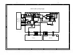
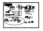
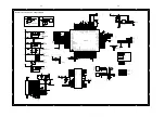
Power Board Circuit Diagram:
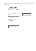
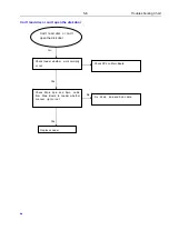
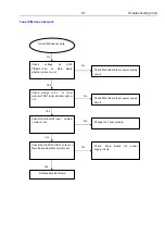
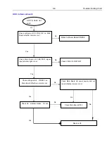
Summary of Contents for HTS2512/94
Page 12: ...AUDIO L R R L AUDIO IN L R AUDIO OUT VIDEO AUDIO L R VIDEO OUT VIDEO IN 2 4 ...
Page 16: ...2 1 2 8 ...
Page 43: ...7 11 7 11 Front Control Board Print layout Bottom Side ...
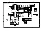
Page 44: ...7 12 7 12 Power Supply Print layout Bottom Side ...
Page 45: ...7 13 7 13 Main Board Print layout Top Side ...
Page 46: ...7 14 7 14 Main Board Print layout Bottom Side ...
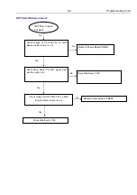
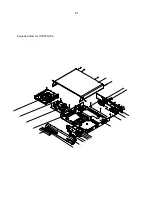
Page 47: ...8 1 Exploded View for HTS2512 94 ...
Page 48: ...REVISION LIST Version 1 0 9 1 Initial release for HTS2512 94 ...