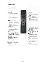
OPERATING CONTROLS AND FUNCTIONS
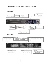
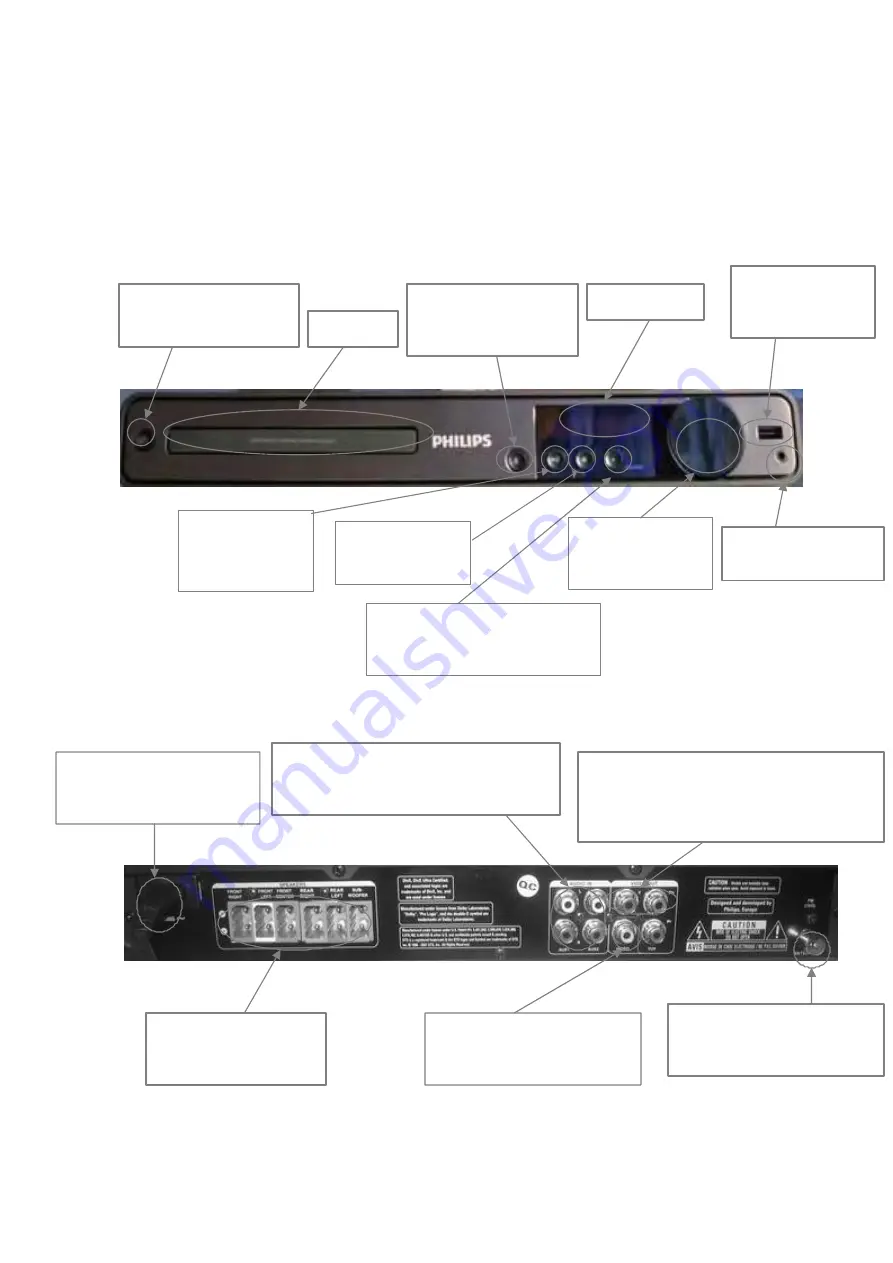
Front Panel
USB
Standby-On
—
Turns on the player or
switches to standby mode
Disc Tray
Open/Close
—
Opens or closes the disc
compartment.
Display Panel
—
Connects a USB
supported device
Play/Pause
Stop
—starts or pauses
—Stops playback
playback
SOURCE
—
Selects a media to play or listen to
audio from the connected device.
Back Panel
VOLUME
—
Increases or
decreases volume.
MIC
—
Connects a microphone
MAINS~(AC Power cord)
—Connect to a standard
AC outlet
SPEAKERS
AUDIO IN
—Connect the audio cables(not supplied)
to the AUDIO IN_AUX1 jacks
VIDEO
VIDEO OUT
—Connect the component video cable(not
supplied) to the Y Pb Pr jacks
ANTENNA
—Connect the Speakers
to the matching jacks
—Connect a composite video
cable to the video jack
—Connect the FM antenna to
the FM 75
Ω
jack
2 - 3
Summary of Contents for HTS3021/94
Page 14: ...3 4 ...
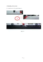
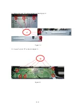
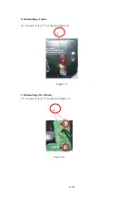
Page 18: ...3 Dismantling of 3 1 Loosen 4 screws B as shown in figure 3 1 Figure 3 1 B 4 3 led key board ...
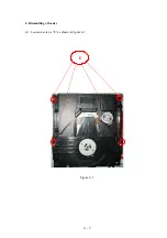
Page 20: ...4 Dismantling of loader 4 1 Loosen 4 screws E as shown in figure 4 1 E Figure 4 1 4 5 ...
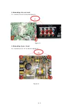
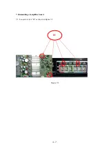
Page 22: ...7 Dismantling of amplifier board 7 1 Loosen 4 screw H as shown in figure 7 1 Figure 7 1 H 4 7 ...
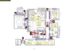
Page 24: ...5 1 C4 C2 C1 C3 C5 C6 C7 C8 C10 C11 C13 C12 BLOCK WIRING DIAGRAM C9 ...
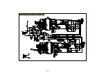
Page 25: ...6 1 AMPLIFIER BOARD SCHEMATIC DIAGRAM 1 3 ...
Page 26: ...6 2 AMPLIFIER BOARD SCHEMATIC DIAGRAM 2 3 ...
Page 27: ...6 3 AMPLIFIER BOARD SCHEMATIC DIAGRAM 3 3 ...
Page 28: ...6 4 AMPLIFIER BOARD TOP VIEW ...
Page 29: ...6 5 AMPLIFIER BOARD BOTTOM VIEW ...
Page 31: ...7 2 LED BOARD TOP VIEW KEY BOARD TOP VIEW LED KEY BOARD TOP VIEW ...
Page 32: ...LED BOARD BOTTOM VIEW KEY BOARD BOTTOM VIEW 7 3 LED KEY BOARD BOTTOM VIEW ...
Page 39: ...8 7 DECODE BOARD TOP VIEW ...
Page 40: ...8 8 DECODE BOARD BOTTOM VIEW ...
Page 42: ...9 2 POWER BOARD TOP VIEW ...
Page 43: ...9 3 POWER BOARD BOTTOM VIEW ...
Page 44: ...10 1 MECHANICAL EXPLODE VIEW ...
Page 51: ...REVISION LIST Version 1 0 Initial release 11 1 ...


