background image

SERVICE MANUAL

BLU-RAY DISC HOME THEATER

HTS3251B/F7

HTS3051B/F7

Summary of Contents for HTS3051B/F7

Page 1: ...SERVICE MANUAL BLU RAY DISC HOME THEATER HTS3251B F7 HTS3051B F7 ...

Page 2: ... done or of the possible hazardous consequences of each way Consequently P F has not undertaken any such broad evaluation Accordingly a servicer who uses a service procedure or tool which is not recommended by P F must first use all precautions thoroughly so that neither his safety nor the safe operation of the equipment will be jeopardized by the service method selected TABLE OF CONTENTS Specific...

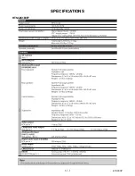
Page 3: ...1 1 1 E1S00SP SPECIFICATIONS HTS3251B F7 ...

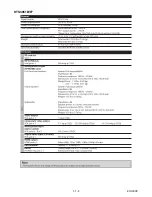
Page 4: ...1 1 2 E1S00SP HTS3051B F7 ...

Page 5: ...way from the pickup lens when the diode is turned on Do not look directly at the laser beam CAUTION Use of controls and adjustments or doing procedures other than those specified herein may result in hazardous radiation exposure Location Inside Top of BD mechanism Do not look directly at the laser beam coming from the pickup or allow it to strike against your skin Drive Mechanism Assembly Laser Be...

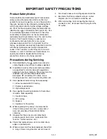
Page 6: ...cal for safety Replace only with part number specified B In addition to safety other parts and assemblies are specified for conformance with regulations applying to spurious radiation These must also be replaced only with specified replacements Examples RF converters RF cables noise blocking capacitors and noise blocking filters etc C Use specified internal wiring Note especially 1 Wires covered w...

Page 7: ...le parts RF terminals antenna terminals video and audio input and output terminals microphone jacks earphone jacks etc is lower than or equal to the specified value in the table below Measuring Method Power ON Insert load Z between B earth ground power cord plug prongs and exposed accessible parts Use an AC voltmeter to measure across the terminals of load Z See Fig 2 and the following table Table...

Page 8: ...achine then apply hot air to the Flat Pack IC about 5 to 6 seconds Fig S 1 1 2 Remove the flat pack IC with tweezers while applying the hot air 3 Bottom of the flat pack IC is fixed with glue to the CBA when removing entire flat pack IC first apply soldering iron to center of the flat pack IC and heat up Then remove glue will be melted Fig S 1 6 4 Release the flat pack IC from the CBA using tweeze...

Page 9: ...by one using a sharp pin or wire to which solder will not adhere iron wire When heating the pins use a fine tip soldering iron or a hot air desoldering machine Fig S 1 4 3 Bottom of the flat pack IC is fixed with glue to the CBA when removing entire flat pack IC first apply soldering iron to center of the flat pack IC and heat up Then remove glue will be melted Fig S 1 6 4 Release the flat pack IC...

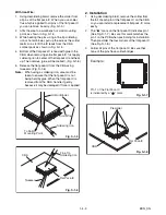
Page 10: ...Fig S 1 6 Note When using a soldering iron care must be taken to ensure that the flat pack IC is not being held by glue When the flat pack IC is removed from the CBA handle it gently because it may be damaged if force is applied 2 Installation 1 Using desoldering braid remove the solder from the foil of each pin of the flat pack IC on the CBA so you can install a replacement flat pack IC more easi...

Page 11: ...ed to remove any static electricity that may be charged on the body 2 Ground for Workbench Be sure to place a conductive sheet or copper plate with proper grounding 1 MΩ on the workbench or other surface where the semi conductors are to be placed Because the static electricity charge on clothing will not escape through the body grounding band be careful to avoid contacting semi conductors with you...

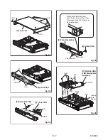
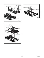
Page 12: ...sembly is adjusted as a unit at factory Therefore do not disassemble it Replace the BD Main CBA BD Mechanism Assembly as a unit ID Loc No Part Removal Fig No Remove Unhook Unlock Release Unplug Desolder Note 1 Top Cover D1 8 S 1 2 Front Unit D2 5 L 1 3 L 2 CN804 1 3 Power SW CBA D3 2 S 2 4 S 3 CN803 CN805 4 Front CBA D3 5 Rotary CBA D4 Volume Knob Nut Washer 6 Front Assembly D4 7 BD Main CBA BD Me...

Page 13: ...BA S 3 CN805 CN803 S 2 Fig D3 From behind the front panel push the two holes with a driver or hexagonal wrench to remove the volume knob 5 Rotary CBA 6 Front Assembly Washer Volume Knob Nut Fig D4 7 BD Main CBA BD Mechanism Assembly CN404 CN6101 CN7001 S 4 M PCB Plate Earth S 6 S 5 S 5 Locking Card Spacer Fig D5 ...

Page 14: ...0DC 8 Fan Cover 9 Rear Panel CN5001 Fan Earth Plate S 8 S 9 S 8 S 10 S 11 S 7 Fig D6 10 AV CBA 11 AMP PSU CBA CN402 CN403 PCB Bracket Front CN9002 S 12 S 13 S 13 Fig D7 12 SD Card CBA 13 MP3 CBA S 14 S 15 Fig D8 ...

Page 15: ...p Cover Front Assembly BD Main CBA BD Mechanism Assembly and PCB Bracket Front 2 Slide the portion A in the direction of the arrow 3 Pull the tray out manually and remove a disc PCB Bracket Front BD Main CBA BD Mechanism Assembly Front Assembly Portion A ...

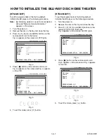
Page 16: ...ctory default initialize the BD player as the following procedure 1 Turn the power on 2 Remove the disc on the tray and close the tray 3 Press 1 2 3 4 and INFO buttons on the remote control unit in that order Fig a appears on the screen All VFD lights Fig a 4 Press C button on the remote control unit Fig b appears on the screen and Fig c appears on the VFD Fig b Fig c 5 To exit this mode press but...

Page 17: ...1 of Fig c is described as follows Fig e Version Up Mode Fig f VFD in Version Up Mode 5 After programming is finished the checksum on the VFD Fig g Fig g VFD upon Finishing the Programming Mode Example Checksum appears on the VFD then the tray will open automatically Remove the disc on the tray At this time no button is available 6 Unplug the AC cord from the AC outlet Then plug it again 7 Turn th...

Page 18: ...s on the remote control unit in that order Fig h appears on the screen Fig h 4 To exit this mode press button differ depending on the models F W Name Version Region Pickup ESN DRM Version Info OK EXIT POWER EEPROM CLEAR STOP HTS3251B F7 HTS3051B F7 differ depending on the models F W Name Version Region Pickup Version Info EXIT POWER EEPROM CLEAR STOP ...

Page 19: ...in Fig i on the VFD Fig h Fig i VFD in Update Mode 8 GOODBYE on the VFD and power turns off automatically when it finishes 9 The power turns on and the tray will open automatically Remove the disc on the tray Note The setup setting configured before the update will be kept Software Upgrade Please insert a disc for software upgrade If you want to exit upgrade press BACK Software Upgrade Loading Dis...

Page 20: ...defective Yes FLOW CHART NO 2 The fuse blows out After servicing replace the fuse F9000 Check the presence that the primary component is leaking or shorted and replace AMP PSU CBA if defective Check the presence that the rectifying diode or circuit is shorted in each rectifying circuit of secondary side and replace AMP PSU CBA if defective CN9001 CN9001 CN9001 CN9001 CN9001 CN9001 1 8V 5V 1 2V 10 ...

Page 21: ...ART NO 4 Audio does not appear normally Set the disc on the disc tray and playback Yes Are the audio signals serial data outputted to Pin 3 4 5 6 of CN201 Replace BD Main CBA BD MECHANISM ASSEMBLY Replace AMP PSU CBA Yes No ...

Page 22: ... Code are shown in the list below The Detailed Error Code shows the three digit code used in the HTTP Status Code or used internally in the Application The HTTP Status Codes 200 to 500 series are defined in the RFC2616 Depending on the specification of the station or the server error codes not listed in the table may appear Network Error Play back Error NE 00103203 OK Network Error Connection Erro...

Page 23: ... this unit 502 Bad Gateway The proxy server between this unit and the server received an invalid reply from another proxy or the original server 503 Service Unavailable Because of overloading or maintenance the server is temporarily unavailable Status Code Description 001 Nothing List As a result of list creation process there is no item to be displayed from the received data 002 LAN Disconnect Th...

Page 24: ...rtage internal cURL pro cessing error 728 Response Timeout A response timeout occurred to unit s connection request 743 System Error Program A system error occurred in the unit program error internal cURL processing error 745 System Error LAN Port A system error occurred in the unit LAN unusable internal cURL processing error 752 Response Timeout A response timeout occurred to unit s connection re...

Page 25: ... IC202 IPOD Certification TU_SDA TU_SCL TU_SDA TU_SCL TU_SDA TU_SCL SCL SDA W_SDA W_SCL SW SDOUT2 4 W_TSD1 3 W_SCLK W_SCLK MCLK XL201 8MHz CN204 5pin CN205 7pin debug1 5 EV 3V3 3 3V UART5_TX UART5_RX upgate_SW FAN Control AD FAN_LOCK CEC SAFETY CEC IN CEC OUT H_DETECT H_DETECT H_MUTE POWER_C 5086_BK_ERR 5086_MUTE PW_ON PW_SW1 PW_SW2 PW_SW3 PW_SW4 PW_SW5 5352_OTW 5352_SD 5086_BK_ERR SW 5086_RST IC2...

Page 26: ... replacement parts that do not have the same safety characteristics as specified in the parts list may create shock fire or other hazards Notes 1 Do not use the part number shown on these drawings for ordering The correct part number is shown in the parts list and may be slightly different or amended since these drawings were prepared 2 All resistance values are indicated in ohms K 103 M 106 3 Res...

Page 27: ...supply Otherwise it may cause some components in the power supply circuit to fail 3 Note 1 Do not use the part number shown on the drawings for ordering The correct part number is shown in the parts list and may be slightly different or amended since the drawings were prepared 2 To maintain original function and reliability of repaired units use only original replacement parts which are listed wit...

Page 28: ...DVSS 10 SDIN1 11 SDIN2 12 SDIN3 13 SDIN4 14 SDA1 15 SCL1 16 SDA2 17 SCL2 18 LRCLK 19 SCLKIN 20 MCLKO 21 SCLKOUT1 22 SCLKOUT2 23 SDOUT4 24 SDOUT3 25 SDOUT2 26 SDOUT1 27 VR_DIG 28 DVSS 29 DVDD 30 PDN 31 RESET 32 RESEVED 33 PLL0 34 PLL1 35 PLL2 36 RESERVED 37 AVDD 38 IC5003 IC_TAS3108 C229 220U 16V C234 104 AV 5V_2 FB215 600 AV 12V FB212 600 AV 12V 3 3V 1 2 3 4 5 6 7 8 9 10 11 12 13 14 GND 16 GND 15 ...

Page 29: ...3A C9056 104P L9007 L 6UH 3A C9055 104P L9006 L 6UH 3A C9054 104P U5V 5V 1 5V 2 D9017 1N4148 D9015 1N4148 D9016 1N4148 C9153 470U 10V C9152 470U 10V C9151 470U 10V R9035 10K BK3V3 Safety C9142 104P 100V 1 2 3 4 5 6 7 8 9 10 11 12 13 14 15 16 17 18 19 20 21 22 23 24 25 26 27 28 29 30 CN9001 CN15P 20 2 SD CMD SD CLK SD DATA3 SGND SD DAT2 SD CD SD WP SD DAT1 SD DAT0 5V 2 3V3 3V3 SGND SGND SGND D S G ...

Page 30: ...0K R466 10K R476 10K R473 10K FB403 0 R403 33R IPOD Det 3 3V 3 3V 3 3v R314 10K V_MUTE1 V_MUTE1 SD HD_LPFSW MP3 INPUT FB305 600 OHM IN 12V IN 12V 3 2 1 B 4 IC401A JRC4558 7 5 6 B 8 IC401B JRC4558 IN 12V IN 12V FB306 600 OHM C439 0 1UF C438 100UF AV 5V_2 AV 5V S 6 VCC 5 Y 4 I0 3 GND 2 I1 1 IC306 Open S 6 VCC 5 Y 4 I0 3 GND 2 I1 1 IC307 Open VIGND VIGND IPOD 5V VCC 1 DET 2 RX 3 GND 4 R 5 TX 6 GND 7 ...

Page 31: ...G12 KS12 25 SG13 KS13 26 SG14 KS14 27 SG15 KS15 28 SG16 KS16 29 SG17 KS12 31 SG18 KS11 32 SG19 KS10 33 VEE 30 SG20 GR9 34 SG21 GR8 35 SG22 GR7 36 SG23 GR6 37 SG24 GR5 38 GR4 39 GR3 40 GR2 41 GR1 42 VDD 43 VSS 44 IC801 PT6315 F2 F1 1 2 3 4 5 6 7 8 9 10 11 12 CN807 FFC 1 0MM DATA3 1 CMD 2 VSS1 3 VDD 4 CLK 5 VSS2 6 DATA0 7 DATA1 8 DATA2 9 DET 10 WP 11 SD801 SD CARD SD CMD SD CLK SD DAT3 GND SD DAT2 S...

Page 32: ...VSSQ E7 VSSQ F2 VSSQ F8 VSSQ H2 VSSQ H8 VSSDL J7 CK J8 CK K8 CKE K2 NC A2 NC E2 BA2 L1 NC R3 NC R7 NC R8 IC6501 K4T1G164QQ HCE7 BA0 L2 BA1 L3 A12 R2 A11 P7 A10 AP M2 A9 P3 A8 P8 A7 P2 A6 N7 A5 N3 A4 N8 A3 N2 A2 M7 A1 M3 A0 M8 UDM B3 LDM F3 UDQS A8 UDQS B7 LDQS E8 LDQS F7 DQ15 B9 DQ14 B1 DQ13 D9 DQ12 D1 DQ11 D3 DQ10 D7 DQ9 C2 DQ8 C8 DQ7 F9 DQ6 F1 DQ5 H9 DQ4 H1 DQ3 H3 DQ2 H7 DQ1 G2 DQ0 G8 RAS K7 CAS...

Page 33: ... CK27XI B19 CK27XO E20 CK74A C20 VC27A D20 AEXCKA T34 XRST AC30 XSRST R6714 10K 1005 R6008 56 1005 R6009 56 1005 R6701 10K 1005 DGND R6012 2 2K 1005 R6062 10K 1005 R6063 10K 1005 R6067 10K 1005 R6066 10K 1005 R6061 10K 1005 R6057 10K 1005 R6058 10K 1005 R6060 10K 1005 R6059 10K 1005 R6056 10K 1005 R6079 2 2K 1005 R6081 2 2K 1005 R6078 2 2K 1005 R6077 2 2K 1005 R6080 2 2K 1005 R6082 2 2K 1005 R6084...

Page 34: ...C7515 47P DGND PON 3V3_BE C7550 47P C7551 47P C7552 47P C7553 47P L7511 OPEN 2125 L7513 OPEN 2125 L7514 OPEN 2125 L7512 OPEN 2125 C7554 47P L7501 R SHORT 1608 R7557 R SHORT R7541 56 1005 R7543 56 1005 C7521 0 1 F C7528 0 1 F R7546 10K 1005 R7539 10K 1005 R7538 10K 1005 R7544 10K 1005 R7545 0 1005 R7548 0 1005 R7559 6 8K 1005 D7502 22P CH 1608 47 6 3V WX C7534 C7519 10 2125 IC7501 MN864707 1 PCLKIN...

Page 35: ... R7602 47 1005 R7603 47 1005 TP7111 TP7106 TP7115 R7606 33 1005 L7601 R SHORT 1608 L7602 R SHORT 1608 L7603 R SHORT 1608 DGND TP7611 TP7612 TP7613 TP7614 TP7615 R7120 0 1608 CN7601 BM05B SRSS TB LF SN 1 5V 2 DN 3 DP 4 GND 5 FG C7022 0 1 F 1005 R7601 0 1608 R7101 82 F R7103 82 F R7105 82 F R7107 82 F VG VG VG AG R7630 0 1608 PON 3V3_BE AUDIO 5V BD2224G IC7601 VIN GND EN OC VOUT R7009 2 2K 1005 R700...

Page 36: ...K9 VDDIO AL1 VDDIO AL12 VDDIO AL15 VDDIO AL18 VDDIO AL2 VDDIO AL6 VDDIO AM11 VDDIO AM5 VDDIO AA6 VDDIOCK AF6 VDDIOCK AJ14 VDDIOCK B1 VDD33 C2 VDD33 D3 VDD33 E4 VDD33 F11 VDD33 F15 VDD33 F20 VDD33 F23 VDD33 F5 VDD33 F8 VDD33 G6 VDD33 J6 VDD33 N13 VDD33 N14 VDD33 N29 VDD33 P13 VDD33 P29 VDD33 R29 VDD33 AC29 VDD33 D26 AVDD33A E26 AVSSA D25 AVDD33A1 E25 AVSSA1 F33 AVDD33D1 G32 AVSSD1 F32 AVDD33DRC L31...

Page 37: ...F 1608 R6439 49 9 F 1608 R6446 33K 1005 D6401 SML 310VTT86K D6402 SML 310VTT86K IC6401 KSZ8041TL 1 GND 2 GND 3 GND 4 VDDA_1 8 5 VDDA_1 8 6 V1 8_OUT 7 VDDA_3 3 8 VDDA_3 3 9 RX 10 RX 11 TX 12 TX 13 GND 14 XO 15 XI 16 REXT 17 GND 18 MDIO 19 MDC 20 RXD3 21 RXD2 22 RXD1 23 RXD0 24 GND 25 VDDIO_3 3 26 VDDIO_3 3 27 RXDV 28 RXC 29 RXER 30 GND 31 VDD_1 8 32 INTRP 33 TXC 34 TXEN 35 TXD0 36 TXD1 37 GND 38 TX...

Page 38: ..._MTR B25 FG B24 P37 PS C21 NEJECT TSM A20 P33 F34 LDDSAVE M30 LDDENA A22 PWM5B E22 PWM6B F28 LPC2 C29 LPC1 F27 LPCO2 E27 LPC3 C28 LPCO1 D27 LPCO3 TP349 CTL_MTR TP348 PS R362 10K TP201 AIN TP202 BIN TP203 CIN TP204 DIN TP206 FIN TP205 EIN TP208 HIN TP207 GIN TP209 RFA TP210 RFB TP211 BDRFA TP212 BDRFB TP213 PAD5 TP216 PAD2 TP214 PAD1 TP221 VREFPD2 TP215 PAD3 TP218 VPD TP220 VPD2 TP219 VREFPD TP223 ...

Page 39: ...O 3 SBT 3 AO2_LRCK_ADAC AIN_L PWM_MUTE AO2__DATA3_ADAC SB3_PIO AIN_PDN AIN_R AO2__DATA0_ADAC AO2_BCK_ADAC AIN_SCLK AIN_LRCK AO2__DATA1_ADAC G_SCL3 AIN_MCLK CEC RDY AIN_SDATO L7201 0 L7202 0 DGND C7333 0 1 F C7334 0 01 F AG C7211 0 1 F C7212 0 1 F C7213 0 1 F DGND R7224 0 1005 R7225 0 1005 DGND CVBS_OUT RXD1 TXD1 R7045 0 1005 R7044 0 1005 R7046 0 1005 R7047 0 1005 CN7001 1 2 3 4 5 6 7 8 9 10 11 12 ...

Page 40: ...02 0 1 F C7303 10 2125 C7301 0 01 F C7304 0 1 F C7305 0 1 F C7306 0 1 F DGND C7307 0 01 F C7310 0 1 F C7308 0 1 F C7309 10 2125 C7311 0 01 F C7312 0 01 F C7313 0 1 F C7314 0 1 F C7315 0 1 F C7316 0 1 F DGND C7317 0 1 F 10 16V WX C7318 10 16V WX C7319 C7320 0 039 C7321 0 47uF PON 1V8_PVDD PON 3V3_BE_AVDD PON 3V3_BE_DVDDIO PON 1V8_DVDD R7326 0 1005 DGND R7327 10K 1005 R7329 10K 1005 C7324 0 01 F R73...

Page 41: ... Otherwise it may cause some components in the power supply circuit to fail NOTE The voltage for parts in hot circuit is measured using hot GND as a common terminal Ce symbole reprèsente un fusible à fusion rapide CAUTION For continued protection against fire hazard replace only with the same type fuse ATTENTION Pour une protection continue les risqes d Incele n utiliser que des fusible de même ty...

Page 42: ... some components in the power supply circuit to fail NOTE The voltage for parts in hot circuit is measured using hot GND as a common terminal Ce symbole reprèsente un fusible à fusion rapide CAUTION For continued protection against fire hazard replace only with the same type fuse ATTENTION Pour une protection continue les risqes d Incele n utiliser que des fusible de même type Risk of fire replace...

Page 43: ...1 11 18 AV CBA Top View ...

Page 44: ...1 11 19 PIN 29 OF CN404 WF3 PIN 27 OF CN404 WF2 PIN 25 OF CN404 WF1 PIN 23 OF CN404 WF4 AV CBA Bottom View ...

Page 45: ...1 11 20 Front CBA Top View Front CBA Bottom View ...

Page 46: ...1 11 21 Power SW CBA Top View MP3 CBA Bottom View MP3 CBA Top View SD Card CBA Top View SD Card CBA Bottom View Power SW CBA Bottom View Rotary CBA Bottom View Rotary CBA Top View ...

Page 47: ...1 11 22 BD Main CBA Top View Not Used ...

Page 48: ...1 11 23 BD Main CBA Bottom View Not Used ...

Page 49: ... Pin 23 of CN404 Component Component Cb Cb 0 2V 0 2V 20 20µsec sec Component Component Cr Cr 0 2V 0 2V 20 20µsec sec WF2 Pin 27 of CN404 Component Y Component Y 0 2V 0 2V 20 20µsec sec CVBS CVBS 0 5V 0 5V 20 20µsec sec NOTE Input COLOR BAR SIGNAL WITH 1KHz AUDIO SIGNAL ...

Page 50: ...F IN 20 21 DGND 21 22 VOGND 22 23 CVBS OUT 23 24 VOGND 24 25 Component Y OUT 25 26 VOGND 26 27 Component Cb OUT 27 28 VOGND 28 29 Component Cr OUT 29 30 VOGND 30 CN6101 CN9001 1 PON 1V8 1 2 PON 1V8 2 3 PON 1V8 3 4 PON 5V 1 4 5 SGND 5 6 USB 5V 6 7 GND 7 8 GND 8 9 PON 1V2 9 10 PON 10V5 10 11 PON 1V2 11 12 PON 10V5 12 13 PON 1V2 13 14 GND 14 15 GND 15 16 GND 16 17 GND 17 18 GND 18 19 PON 3V3 19 20 PO...

Page 51: ...13 2L002 B1 B11 2L022 2L021 B20 2L023 2L024 A6 A2 A6 2L031 B21 2L030 2L030 A7 A1X 2L050 2L051 A21 A20 A22 Front CBA AV CBA AMP PSU CBA Power SW CBA BD Main CBA BD Mechanism Assembly SD Card CBA Rotary CBA MP3 CBA 2L005 2L008 2L006 2L008 A6 B12 B12 See Electrical Parts List for parts with this mark B21 ...

Page 52: ...1 14 2 E1S00PEX Packing HTS3251B F7 S2 X3 X22 X21 A30 Lower Side Upper Side X20 X2 X7 X5 S3 S1 B S4 S10 S1 A X10 X1 A21 A21 A21 Some Ref Numbers are not in sequence A23 A21 ...

Page 53: ...1 14 3 E1S02PEX HTS3051B F7 S2 A23 A21 X3 X21 A30 X20 X2 X7 X5 S1 B A31 X10 S1 A X1 S3 X6 A21 A21 A21 Some Ref Numbers are not in sequence ...

Page 54: ...20 SCREW C TIGHT M3X6 E5610UD 0VM412937A 2L021 SCREW C TIGHT M3X6 E5610UD 0VM412937A 2L022 SCREW C TIGHT M3X6 E5610UD 0VM412937A 2L023 SCREW C TIGHT M3X6 E5610UD 0VM412937A 2L024 SCREW C TIGHT M3X6 E5610UD 0VM412937A 2L030 SCREW P TIGHT M3X8 BIND HEAD GBJP3080 2L031 SCREW P TIGHT M3X8 BIND HEAD GBJP3080 2L040 SCREW S TIGHT M3X10 E5610UD 0VM412936A 2L050 WASHER E1S00UD 1VM435260 2L051 NUT E1S00UD 1...

Page 55: ...els and Marks BD MAIN CBA BD MECHANISM ASSEMBLY AV CBA AMP PSU CBA FRONT CBA SD CARD CBA MP3 CBA POWER SW CBA ROTARY CBA C 0 25 D 0 5 F 1 G 2 J 5 K 10 M 20 N 30 Z 80 20 Model Mark HTS3251B F7 A HTS3051B F7 B Ref No Mark Description Part No A BD MAIN CBA BD MECHANISM ASSEMBLY N77P5CUN B BD MAIN CBA BD MECHANISM ASSEMBLY N77P7CUN Ref No Description Part No AV CBA UPB000ESC001 Ref No Description Part...

Page 56: ...thout the obligation to notify any person or organization of such changes with the design is a registered trademark of Funai Electric Co Ltd and may not be used in any way without the express written consent of Funai All other trademarks used herein remain the exclusive property of their respective owners Nothing contained in this manual should be construed as granting by implication or otherwise ...

Page 57: ...l shows only the differences between the HTS3051BV F7 model and the original model HTS3051B F7 All other information is described in the service manual of the original model HTS3051B F7 BLU RAY DISC HOME THEATER HTS3051BV F7 SUPPLEMENT ...

Page 58: ...nsent of Funai Furthermore any unauthorized commercial distribution of this manual or any revision hereto is strictly prohibited Information in this document is subject to change without notice Funai reserves the right to change the content herein without the obligation to notify any person or organization of such changes with the design is a registered trademark of Funai Electric Co Ltd and may n...

Reviews: