background image

1-12-13

com

out

in

STEPDA

P17

CLOSESW

SOT0

STEPDA

LDON

SENSJ2

EXPA-

P22

NPDIAG

P04

LDCNT

SIN0

BXB+

EXPA+

TRD+

FG

SDIO

FD2

P20

PG

MASTER

SOT0

SPINDLE

DSEN

TR

SENSJ1

SCLK

FOD1+

TD

P17

FOD2+

MSTPOL

NDASP

FR1

NPDIAG

NDASP

LDCNT

FD1

BXA+

BXB+

DASPST

TRD+

P04

FR2

DASPST

FG

P22

FOD2+

P20

STEPDB

SPINDLE

FOD1+

BXA+

EXPB-

SIN0

MSTPOL

SENSJ1

STEPDB

SA_INT

EXPB+

MASTER

SENSJ2

TD

EXPA+

EXPB-

EXPA-

DSEN

EXPB+

FD1

FR1

TR

FR2

SA_INT

SCLK

LDON

SDIO

FMSW

FD2

OPENSW

DGND

R351

1.5[3216]

TP340

D3.3V

C207

1[B]

R358

OPEN[2125]

TP334

R349

BK1005HM102

TP262

SVREF

C350

0.1[F]

R336

47K

PG

DIN

TP332

PG

C209

1[F]

P17

TP201

AIN

PON+5V_FE

47/16V(WX)

C403

G_TCK

R327

12K

A5V

VHALF

R357

P_S[2125]

TP204

DIN

TP210

RFB

TP213

PAD5

C805

100P[CH]

TP208

HIN

C318

0.01

R219

4.7K

AIN

AIN_MCLK

TP221

VREFPD2

C339

68P

C335

1000P

VHALF

TMS

C320

0.01

TP220

VPD2

TP228

PO6

MOUT2

TP342

MOUT0

TP335

TP222

IREAD

TP317

STEPDB-

C348

0.1[F]

PG

R217

100K

C333

OPEN

MOUT1

R404

0

C408

0.1[F]

TP321

IC TBXA+

AVCC

R350

180

TP252

RVREF

DGND

C513

82P[CH]

C331

1000P

C213

0.1[F]

MOUT0

IC301

AM9858

1

VCC5

2

GND

3

HGND

4

FG

5

MU1

6

MU2

7

Cd

8

VDO

9

OSC

10

SPIN

11

VREF

12

HB

13

HU+

14

HU-

15

HV+

16

HV-

17

HW+

18

HW-

19

U

20

GND

21

V

22

PGND

23

PGND

24

W

25

RSP

26

RSP1

27

VM1

28

VM12

29

FIN

30

FIN

IC302 AM9268

25

11

30

16

1

22

21

7

3

27

13

35

32

18

4

24

10

36

9

29

15

20

6

26

12

2

31

17

23

8

28

14

34

33

19

5

37

38

39

40

41

42

43

TP249

CWAGCAD

R216

100K

CN801

BM10B-SRSS-TB

Debugger

1

TCK

2

GND

3

XTRST

4

P22

5

TMS

6

TDI

7

TDO

8

EXTRG

9

PON+3V3_BE

10

XRST

R222

10K

THERMOOP

R206

P_S[1005]

PG

C310

2700P

DGND

C308

6800P

R323

4.7K

IC6001

BP1

BP1A

M32

P25/SCLK

M33

P05/DSEN

M31

P24/SDI0

B26

P07/FMSW

N30

P06/LDON

C26

P30/SA_INT

E21

P34/CLOSESW

D21

TRYLOAD/OPENSW

B3

P36/INSW

B22

PWM5A/BXA+

D22

PWM6A/BXB+

C25

P31/MUTE_BEX

C24

PWM3A/STEPDA

D24

PWM3B/STEPDB

A24

PWM1A/FOD1+

D23

PWM0A/FOD2+

E23

PWM2A/TRD+

C22

PWM7/LDCNT

E24

PWM4/SPINDLE

A26

P32/CTL_MTR

B25

FG

B24

P37/PS

C21

NEJECT/TSM

A20

P33

F34

LDDSAVE

M30

LDDENA

A22

PWM5B

E22

PWM6B

F28

LPC2

C29

LPC1

F27

LPCO2

E27

LPC3

C28

LPCO1

D27

LPCO3

BDRFA

DGND

TP259

LPC01

R209

P_S[1005]

47/6.3V(WX)

C204

C306

6800P

TP336

TP401

PON+10V5

LOAD-

TP207

GIN

TP255

VREFH

SPDIF_IN

TP246

REFMDLA

TP807

P01

L402
BKP2125HS221

VHALF

R208

P_S[1005]

C217

0.1

TP226

FPIO4

TP248

CPOP2

R407

P_S[2125]

C317 1000P

C329

82P[CH]

C304

1500PF

THERMOOP

C205

0.1[F]

TP804

SENSJ1

TP328

R212

100K

R409

0[2125]

TP801

XFERST

R513

0

TP349

CTL_MTR

R313

47K

R214

OPEN

CTL_MTR

R330

4.7K

R401

1K[F]

TP323

SPINDLE

TP312

TKIN

CLUMPSW

TP256

LPC1

C344

0.1[F]

TP309
TRD+B

PON+3V3_BE

PG

RFB

C312
2200P

TP240

PO1

C341

10u/10V

C327

1000P

R225

P_S[1005]

TP236

BR_MTR

AIN_SDATO

TP261

LPC03

C201

1[B]

C218

0.1

TP235

PO0

TP231

MOUT0

EXTRG

R803

10K

R227

P_S[1005]

TP402

A8V_REG

TP318
STEPDB

C315 1000P

TP346

C337

0.1[F]

R359

P_S[2125]

VHALF

DGND

PON+10V5

FIN

R325

22K

C405

10u/10V

TP333

R321

P_S[1005]

DGND

C338

0.1[F]

TP331

AIN_SCLK

MSTPOL

TP304

FCIN

C353

150P[CH]

PG

VREF25

R808

10K

R801

10K

R301

47K

PON+10V5

C323

OPEN

TP264

VHALF

PG

C325

1000P

R335

47K

R340

1.5[3216]

R355

1.5

DGND

R324

22K

CIN

C346 180PF

R505

0

47/6.3V(WX)

C219

MOUT2

VHALF

GIN

TP203

CIN

TP263

VREFH

TP212

BDRFB

TP341

TP205

EIN

IC6001

BP1

BP1A

A28

SE01

B28

SE02

M34

FPIO4

L33

PO5

L32

PO6

H30

MOUT2

H31

MOUT1

J31

MOUT0

L34

PO3

K34

PO2

K33

EXMONI1

J32

PO0

J33

FPIO2

J34

FPIO3

H32

FPIO1

H33

FPIO0

H34

PO4

G34

PO1

G33

EXMONI0

D30

PAD0

C33

RFA

B34

RFB

A25

VHALF

E31

VHALFOUT

D32

HDVREF

K31

CDA1

L30

REFMDL

K30

REFMDLA

E33

CPOP1

E34

CPOP2

J30

CWAGCAD

D33

CWAGCBC

F26

CLPCLPF

D28

RVREF

B27

FEMODE

A27

XFERST

C311

0.1[F]

TP214

PAD1

PG

DGND

VC_PD

TP218

VPD

A8V_REG

R381

10K

C211

0.033

IMSA-9611S-06Y916

CN804

1

NRST

2

SIN0

3

SOT0

4

GND

5

SENSJ1

6

SENSJ2

R339

OPEN

TP223

VREF25

TP351

R329

47K

CN802

6266-010

DRC Monitor

1

MASTER

2

MSTPOL

3

DASPST

4

P04

5

P22

6

NDASP

7

P17

8

P20

9

NPDIAG

10

GND

R806

10K

C401

0.1[F]

PG

HIN

R333

4.7K

TP405
D3.3V

MOUT2

P22

R220

10K

A5V

C802

100P[CH]

R322

3.9K

DGND

BDRFB

VHALF

TP251

CLPCLPF

C305

1500PF

TP344

A5V

PON+10V5

R337
4.7K

LOAD+

TP339

DGND

DGND

C208

0.1[F]

VHALF

PG

DASPST

XFERST

TP260

LPC02

L401
BKP2125HS221

TP254

XFERST

47/6.3V(WX)

C210

R805

10K

PG

TP244

CDA1

C345

0.1[F]

DISCIN

PON+10V5

TP408

PG

C404

0.1[F]

MOUT0

PG

DGND

TP225

SE02

VHALF

TP245

REFMDL

R320

51K

VHALF

C804

100P[CH]

C381

0.1[F]

R362

10K

TP803

SOT0

C319

0.01

TP325

SPINDLE_OP

RFA

TP314

FG-

TEST_V

TP311
TRDDR

CTL_MTR

C206

1[B]

TP308

TLIN

R347

180

TP242

PAD0

PG

PON+10V5

PG

PON+3V3_BE

TP345

TP305

FOD2+DB

C215

0.082

C514

82P[CH]

TP238

TSM

CLUMPSW

C321

OPEN

TP237

FPIO3

DGND

TP230

MOUT1

PS

A8V_REG

LOAD-

C349

0.1[F]

TP232

SW3

TP330

XFERST

NPDIAG

C406

0.1[F]

PON+10V5

C334

1000P

R218

100K

TP809

P17

D3.3V

TP224

SE01

C309

OPEN

VHALF

VHALF

MOUT1

TP303

FOD1+DR

220/16V

C340

TDO

R403 1.8K[F]

DGND

P21

TP217

PAD4

TP316

BXB+

C203

0.1[F]

R211

P_S[1005]

TP320
STEPDA

XTRST0

C216

0.1

D3.3V

R215

10K

VHALF

TP202

BIN

C330

1000P

TP319

STEPDA-

DISCOUT

R205

P_S[1005]

R326

12K

TP211

BDRFA

TP206

FIN

PG

TP404
AVCC

R332

4.7K

TP216

PAD2

C202

1[B]

PON+3V3_BE

R410

0[2125]

PG

R408

0[2125]

A8V

VHALF

TP215

PAD3

DISCIN

R221

10K[F]

TP227

PO5

R213

100K

C316 1000P

DGND

R804

10K

TP219

VREFPD

R223

P_S[1005]

DGND

R334

47K

TP315

BXA+

PS

R207

P_S[1005]

R226 P_S[1005]

CN301

2

SLD2-

3

SLD1+

4

SLD1-

1

SLD2+

PG

C354

150P[CH]

EIN

TP343

R402

120[F]

R210

P_S[1005]

TP806

DGND

BIN

VREFH

TP338

P04

C326

1000P

CN803

6266-010

SERVO Monitor

1

P00

2

P01

3

P17

4

P04

5

MOUT0

6

MOUT1

7

MOUT2

8

NC

9

NC

10

GND

DGND

R341

1.5[3216]

R802

10K

NDASP

TP808

P01

R331

4.7K

C322

OPEN

VHALF

C347

0.1[F]

C314 1000P

R328

47K

C214

8200P

TP247

CPOP1

DGND

C313

2200P

TDI

PON+3V3_FE

R356

1.5

R511 0

AIN_LRCK

VHALF

TP403

A5V

TP257

LPC2

P20

D3.3V

C324

0.1[F]

TP253

FEMODE

TP407

DGND

TP209

RFA

C220

0.1[F]

R405

P_S[2125]

R807

10K

R307

47K

TP243

VHALFOUT

PON+10V5

VHALF

TP250

CWAGCBC

TP805

SENSJ2

BR_MTR

TP337

TP348

PS

TP802

SIN0

C352

150P[CH]

TP324

SPINDLE-

C342

0.1[F]

TP313

FG

VHALF

A5V

MOUT1

TP258

LPC3

DISCOUT

VHALF

TP307

FOD2+DR

TP329

BR_MTR

TP241

EXMONI0

IC6001

BP1

BP1A

P30

P31

P33

N33

N32

N34

N31

P32

P34

D19

E19

A23

C23

A21

B21

B23

R32

B20

C19

R31

R30

A30

HIN

A31

EIN

A32

BIN

A33

PAD5

B30

GIN

B31

DIN

B32

AIN

C30

FIN

C31

CIN

C34

SVREF

D29

PAD2

E28

PAD3

E29

PAD1

E30

VPD

F29

PAD4

F30

VREFPD

F31

VPD2

G29

VREFPD2

G30

BDRFB

G31

BDRFA

H29

VREF25

C27

IREAD

LD1117SC

IC401

C212

0.1[F]

DGND

TP239

PO4

R364

10K

TP229

MOUT2

XFERST

TP234

EXMONI1

DGND

C307

6800P

TP233

PO2

TP301

FOD1+B

C803

100P[CH]

PS

R338

4.7K

[1005]

MASTER

PG

DGND

LOAD+

DGND

TP810

P04

BIN

TP121

LD_TYPE

C111

0.1[F]

R115

1K

TP117

TP104

C110

0.1[F]

CIN

DGND

CN101

(TO BD 
MECHANISM 
ASSEMBLY)

(TO BD 
MECHANISM 
ASSEMBLY)

(TO BD 
MECHANISM 
ASSEMBLY)

1

2

3

4

5

6

7

8

9

10

11

12

13

14

15

16

17

18

19

20

21

22

23

24

25

26

27

28

29

30

B

31

32

33

34

35

36

37

38

39

40

41

42

43

44

45

PO0

TP137

DGND

AVCC

R121

2.2K

TP112

L103

BKP2125HS221

TP114

EIN

PO1

TP102

R119

2.2K

R112

1K

R146

P_S[1005]

DGND

FIN

AVCC

R123

2.2K

FPIO1

TP126

TP128

TP115

GIN

TP101

R136

P_S[1005]

R132

100

TP131

R117

1K

DIN

R145

P_S[1005]

R124

2.2K

R131

100

TP122

R111

1K

TP106

TP110

HIN

TP129

TP118

R129

OPEN[2125]

R116

1K

R137

OPEN

Q102
KTC3875S

TP138

R133

100

TP108

Q101

KTC3875S

VC_PD

TP113

TP120

TP134

R118

2.2K

DGND

R110

1K

VC_PD

TP124

TP109

DGND

R134

P_S[1005]

TP119

D3.3V

R120

2.2K

TP136

R113

1K

TP135

R130

100

R127

P_S[1608]

TP125

TP123

A8V

TP105

TP107

RFB

R122

2.2K

TP130

R126

P_S[2125]

TP132

AVCC

VC_PD

AVCC

TEST_V

VREFH

TP127

R135 OPEN

TP116

VHALF

TP103

R114

1K

C112

OPEN

BDRFB

TP133

R107

P_S[1005]

AIN

RFA

R125

2.2K

R144

P_S[1005]

BDRFA

C115

OPEN

DGND

C113

OPEN

C114

OPEN

DGND

L102

P_S[1608]

DGND

C102

0.1[F]

C103

0.1[F]

C104

0.1[F]

C101

0.1[F]

C107

270P[CH]

C106

270P[CH]

C105

270P[CH]

DGND

R312

0

C302

1000p[B]

R308

4.7K

C301

1000p[B]

R302

4.7K

R306

0

R318

0

C303

1000p[B]

R314

4.7K

C351

10(2125)

C402

10(2125)

C407
10(2125)

C221

1[F]

LD_TYPE

R201

OPEN

TP266

FMSW

PO0

R204

0

LD_TYPE

PO1

FPIO1

TP265

FPIO1

R202

0

C343

0.01

R367

0[2125]

R147

4.7K

D3.3V

C120

0.1[F]

TP352

IC TBXB+

R203

P_S[1005]

R501

10K

D3.3V

R507

10K

DGND

C355
680P[BJ]

C356

10[BK]

R319

3K

CN302

1

LOAD-

2

LOAD+

3

DGND

4

DISCOUT

5

DISCIN

6

VH-

7

HW-

8

HW+

9

HV-

10

HV+

11

HU-

12

HU+

13

VH+

14

U

15

V

16

W

TP139

VMCOL

VCC5

CTL2

CTL1

REG_EN

TYIN

OSC

RSL1

GND

SL1N

VCC5

SL1P

SL2IN

BIAS
REGO

HGND

TLIN

PGND

TRB

VCC12

SL1IN

GND

FIN

TYP
TYN

VCC12

SL2P

FCN

FCP

TLN

TLP

FCIN

TKIN

TKN

RSL2

TKP

SL2N

CO1N

CO2P

CO1P

CO1IN

CO2N

CO2IN

R355-R356,C346

MODEC

MODEB

MODEA

TEST_V

LDEN

SEN_LDD

SCLK

SDIO

GND

8V

GND

5V

GND

3.3V

GND

GND/LD_TYPE

VC_PD

GND_PD

BD RF-

BD RF+

GND_PD

DVD RF-

DVD RF+

GND_PD

5V_PD

THERMO

SA_INT

SA A-

SA A+

SA B-

SA B+

FD1

FR1

TR

TD

FD2

FR2

TO BD MAIN 4

TO BD MAIN 2

TO BD MAIN 8

TO BD MAIN 8

TO BD MAIN 2

TO BD MAIN 2

TO BD MAIN 2

TO BD MAIN 2

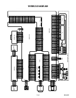
P22

MASTER

MSTPOL

DASPST

P04

NDASP

P17

P20

NPDIAG

P00

P01

PWM0B/SENSJ1

PWM1B/SENSJ2

P16/SOT0

P26/SIN0

PWM2B

P21

P02

P03

P14

P15

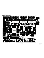
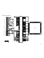
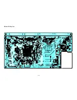
BD Main 7 Schematic Diagram

EDA02SCB7

Summary of Contents for HTS3106/F7 C

Page 1: ...SERVICE MANUAL BLU RAY DISC HOME THEATER HTS3106 F7 C ...

Page 2: ...us consequences of each way Consequently P F has not undertaken any such broad evaluation Accordingly a servicer who uses a service procedure or tool which is not recommended by P F must first use all precautions thoroughly so that neither his safety nor the safe operation of the equipment will be jeopardized by the service method selected TABLE OF CONTENTS Specifications 1 1 1 Laser Beam Safety P...

Page 3: ...ll range satellite Impedance 4 Frequency response 180 Hz 20 kHz Dimensions 3 9 x 5 1 x 4 0 inches 100 x 130 x 100 5 mm Speaker cable length front 9 8 feet 3 m rear 30 feet 9 15 m Weight front 1 19 lbs 0 54 kg rear 1 13 lbs 0 51 kg Center speaker System Full range satellite Impedance 4 Frequency response 180 Hz 20 kHz Dimensions 3 9 x 5 1 x 4 0 inches 100 x 130 x 100 5 mm Speaker cable length 9 8 f...

Page 4: ... 30 cm away from the pickup lens when the diode is turned on Do not look directly at the laser beam CAUTION Use of controls and adjustments or doing procedures other than those specified herein may result in hazardous radiation exposure Location Inside Top of BD mechanism Do not look directly at the laser beam coming from the pickup or allow it to strike against your skin Drive Mechanism Assembly ...

Page 5: ...ther parts and assemblies are specified for conformance with regulations applying to spurious radiation These must also be replaced only with specified replacements Examples RF converters RF cables noise blocking capacitors and noise blocking filters etc C Use specified internal wiring Note especially 1 Wires covered with PVC tubing 2 Double insulated wires 3 High voltage leads D Use specified ins...

Page 6: ...le parts RF terminals antenna terminals video and audio input and output terminals microphone jacks earphone jacks etc is lower than or equal to the specified value in the table below Measuring Method Power ON Insert load Z between B earth ground power cord plug prongs and exposed accessible parts Use an AC voltmeter to measure across the terminals of load Z See Fig 2 and the following table Table...

Page 7: ...achine then apply hot air to the Flat Pack IC about 5 to 6 seconds Fig S 1 1 2 Remove the flat pack IC with tweezers while applying the hot air 3 Bottom of the flat pack IC is fixed with glue to the CBA when removing entire flat pack IC first apply soldering iron to center of the flat pack IC and heat up Then remove glue will be melted Fig S 1 6 4 Release the flat pack IC from the CBA using tweeze...

Page 8: ...by one using a sharp pin or wire to which solder will not adhere iron wire When heating the pins use a fine tip soldering iron or a hot air desoldering machine Fig S 1 4 3 Bottom of the flat pack IC is fixed with glue to the CBA when removing entire flat pack IC first apply soldering iron to center of the flat pack IC and heat up Then remove glue will be melted Fig S 1 6 4 Release the flat pack IC...

Page 9: ...Fig S 1 6 Note When using a soldering iron care must be taken to ensure that the flat pack IC is not being held by glue When the flat pack IC is removed from the CBA handle it gently because it may be damaged if force is applied 2 Installation 1 Using desoldering braid remove the solder from the foil of each pin of the flat pack IC on the CBA so you can install a replacement flat pack IC more easi...

Page 10: ...ed to remove any static electricity that may be charged on the body 2 Ground for Workbench Be sure to place a conductive sheet or copper plate with proper grounding 1 MΩ on the workbench or other surface where the semi conductors are to be placed Because the static electricity charge on clothing will not escape through the body grounding band be careful to avoid contacting semi conductors with you...

Page 11: ...NSTRUCTIONS FOR BD MAIN CBA OR BD MECHANISM ASSEMBLY REPLACEMENT 3 When reassembling be sure to use the original screws or specified screws listed in the parts list ID Loc No Part Fig No Removal Note 1 Top Cover D1 8 S 1 2 Front Unit D2 5 L 1 3 L 2 3 L 3 4 S 2 CN2005 CN2006 CN2007 CN7601 1 3 Front CBA D2 4 Power SW CBA D3 2 S 3 5 WiFi CBA D3 6 Rotary CBA D4 Volume Knob Nut Washer 7 Front Assembly ...

Page 12: ... 3 L 2 Fig D2 4 Power SW CBA 5 WiFi CBA S 3 Cable connected to the WiFi CBA WiFi CBA The cable connected to the WiFi CBA should be placed as shown Fig D3 From behind the front panel push the two holes with a driver or hexagonal wrench to remove the volume knob 6 Rotary CBA 7 Front Assembly Washer Volume Knob Nut Fig D4 ...

Page 13: ...arth S 6 S 5 S 5 Locking Card Spacer CN302 CN301 See Reference Note 2 Fig D5 10 Fan Cover 11 Rear Panel CN5001 Fan Earth Plate S 8 S 9 S 10 S 7 See Reference Note 3 Fig D6 12 AV CBA 13 AMP PSU CBA CN402 CN403 PCB Bracket Front CN9002 S 11 S 12 S 12 Fig D7 14 SD Card CBA 15 MP3 CBA S 13 S 14 Fig D8 ...

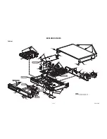
Page 14: ...r on by pressing the A button and the disc tray will open automatically Procedure B 1 Remove the Top Cover and Front Unit 2 Disconnect connector CN7101 on the BD Main CBA 3 Remove the BD Mechanism Assembly 4 Slide the portion A in the direction of the arrow from bottom side of the BD Mechanism Assembly 5 Pull the tray out manually and remove the disc BD Mechanism Assembly Bottom of BD Mechanism As...

Page 15: ...urn the power on 2 Remove the disc on the tray and close the tray 3 Press skip up 1 2 and 3 buttons on the remote control unit in this order Fig a appears on the screen All VFD lights Fig a 4 Press C button on the remote control unit Fig b appears on the screen and Fig c appears on the VFD Fig b Fig c 5 After initializing the power will turn off automatically differ depending on the models F W Nam...

Page 16: ...The power turns back on automatically If disc mode was selected the tray will open automatically Remove the disc or USB Memory Stick or SD Card from the unit Notes All the settings will be put back to factory default Do not unplug the AC cord and do not remove the disc or USB Memory Stick or SD Card while this procedure The following USB Memory Stick SD Card can be used for software update Make su...

Page 17: ...he above procedure please perform the following 1 Write the software downloaded on our website in SD Memory Card 2 Insert the SD Memory Card into the SD card slot 3 Press the STANDBY ON button of this unit for 10 seconds 4 As this unit will turn off press the STANDBY ON button differ depending on the models F W Name Version Region Pickup ESN DRM Version Display OK Default Setting Default Setting S...

Page 18: ...n in Fig o on the VFD Fig n Fig o VFD in Update Mode 10 After the update the power turns off and then turns back on automatically If disc mode was selected the tray will open automatically Remove the disc or USB Memory Stick or SD Card from the unit Note The setup setting configured before the update will be kept The following USB Memory Stick SD Card can be used for software update Make sure to u...

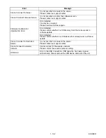
Page 19: ... a few minutes During the updated process the player will automatically turn off and turn back on No Error Message 1 The cable is not connected Please confirm the connection of the cable 2 DHCP cannot be acquired Please confirm connection or set it with the manual operation 3 Internet Protocol address is not set Please confirm the set content 4 The equipment with same Internet Protocol address alr...

Page 20: ...ed application OpuDataWriter Caution Always turn the unit power off before connecting the FFC cable or removing the FFC cable from the BD Main CBA 1 Preparation Of Work Environment 1 1 For the OPU DATA write operation refer to the connection diagram and connect each device as shown below Connection Diagram Unit Completed product BD Main CBA BD Mechanism Assembly COMTOOL Jig Relay Board USB cable T...

Page 21: ...eck the box for Include this location in the search 5 Click on Browse button then select the device driver CDM 2 06 00 WHQL Certified folder in the C drive Click Next 6 Confirm that installation of USB Serial Converter device driver has completed and click on Finish 2 How To Check Which Port Is Used For COMTOOL Jig Relay Board 2 1 Click on the Windows Start button on the PC 2 2 Right click on My C...

Page 22: ...nput OPU DATA message is displayed in the Status Display Set the cursor position at the blank box next to the OPU DATA 4 4 Using the Barcode reader scan the QR code attached on the side of the BD Mechanism Assembly 4 5 Check that FE CONNECTION CHECK message appears on the Status Display then turn the unit power on If error occurs If an error occurs the screen changes to a red display In such case ...

Page 23: ... unit AC power cord Check if each device is properly connected then repeat from step 1 If an error other than connection error occurs for more than 3 times the BD MAIN CBA or BD Mechanism Assembly may be defected Replace with a new one before performing the OPU DATA write 4 8 After data write has been completed successfully unplug the AC power cord 4 9 Remove the FFC Cable of COMTOOL jig relay boa...

Page 24: ... S N could not be found 1140 DDDFile search error Error occurred while searching DDD file in WriteBackup folder 1151 WriteBackup Drive Mount error Cannot mount the drive set for WriteBackup folder 1152 Transfer Drive Mount error Cannot mount the drive set for Transfer folder 1153 OpuData Drive Mount error Cannot mount the drive set for OpuData folder 1154 Log Drive Mount error Cannot mount the dri...

Page 25: ...LD Parameter 2044 LdParamClear TIME OUT Cannot initialize LD Parameter TimeOut 2051 IopSet NG Iop Set Error 2052 IopSet ERROR0 Iop Set Error 2053 IopSet ERROR1 Iop Set Error 2054 IopSet TIME OUT lop Set Error TimeOut 2055 IopSet ERROR0 Iop Set Error 2056 IopSet ERROR1 Iop Set Error 2057 IopSet TIME OUT lop Set Error TimeOut 2058 CD Iop LIMIT NG CD Iop exceeds limit value 2059 DVD Iop LIMIT NG DVD ...

Page 26: ...ctive Yes FLOW CHART NO 2 The fuse blows out After servicing replace the fuse F9000 Check the presence that the primary component is leaking or shorted and replace AMP PSU CBA if defective Check the presence that the rectifying diode or circuit is shorted in each rectifying circuit of secondary side and replace AMP PSU CBA if defective CN9001 CN9001 CN9001 CN9001 CN9001 CN9001 1 8V 5V 1 2V 10 5V 3...

Page 27: ...T NO 4 Audio does not appear normally Set the disc on the disc tray and playback Yes Are the audio signals serial data outputted to Pin 3 4 5 6 of CN201 Replace BD Main CBA or BD MECHANISM ASSEMBLY Replace AMP PSU CBA Yes No ...

Page 28: ...mory Device or Device has incorrect no format BD Live Network Connecting Error BD Live Setting Error Network connection is interrupted Please confirm BD Live Setting LAN Cable Not Connected The cable is not connected Please confirm the connection of the cable Cannot Acquire DHCP Server DHCP cannot be acquired Please confirm connection or set it with the manual operation Cannot Acquire IP Address I...

Page 29: ...ected Please confirm whether it is SD Memory Card that corresponds to software update Error detected Please confirm whether it is USB device that corresponds to software update Cannot Connect To Download Server It is not possible to connect to the server Please contact our support center Cannot connect to wireless network Cannot connect to the wireless network Please confirm the wireless network s...

Page 30: ..._SCLK W_SCLK MCLK XL201 12MHz CN204 5pin CN205 7pin debug1 5 EV 3V3 3 3V UART5_TX UART5_RX upgate_SW FAN Control AD FAN_LOCK CEC SAFETY CEC IN CEC OUT H_DETECT H_DETECT H_MUTE POWER_C 5086_BK_ERR 5086_MUTE PW_ON PW_SW1 PW_SW2 PW_SW3 PW_SW4 PW_SW5 5352_OTW 5352_SD 5086_BK_ERR SW 5086_RST IC203 COM SAFETY A 5V EV 3V3 SAFETY 34V AV 12V AV 12V EV 3V3 3V3 FAN SW Inductor 3 3V DV33 IC5006 EEPROM SD DAT0...

Page 31: ... replacement parts that do not have the same safety characteristics as specified in the parts list may create shock fire or other hazards Notes 1 Do not use the part number shown on these drawings for ordering The correct part number is shown in the parts list and may be slightly different or amended since these drawings were prepared 2 All resistance values are indicated in ohms K 103 M 106 3 Res...

Page 32: ...supply Otherwise it may cause some components in the power supply circuit to fail 3 Note 1 Do not use the part number shown on the drawings for ordering The correct part number is shown in the parts list and may be slightly different or amended since the drawings were prepared 2 To maintain original function and reliability of repaired units use only original replacement parts which are listed wit...

Page 33: ...2 SDIN3 13 SDIN4 14 SDA1 15 SCL1 16 SDA2 17 SCL2 18 LRCLK 19 SCLKIN 20 MCLKO 21 SCLKOUT1 22 SCLKOUT2 23 SDOUT4 24 SDOUT3 25 SDOUT2 26 SDOUT1 27 VR_DIG 28 DVSS 29 DVDD 30 PDN 31 RESET 32 RESEVED 33 PLL0 34 PLL1 35 PLL2 36 RESERVED 37 AVDD 38 IC5003 IC_TAS3108 C229 220U 16V C234 104 AV 5V_2 FB215 600 AV 12V FB212 600 AV 12V 3 3V 1 2 3 4 5 6 7 8 9 10 11 12 13 14 GND 16 GND 15 JK201 WIRELESS JACK C219...

Page 34: ...21 22 23 24 25 26 27 28 29 30 CN9001 CN15P 20 2 SD CMD SD CLK SD DATA3 SGND SD DAT2 SD CD SD WP SD DAT1 SD DAT0 5V 2 3V3 3V3 SGND SGND SGND TO BD MAIN CBA CN6101 TO SD CARD CBA CN807 D S G Q9001 13N50C D S G Q9002 13N50C 1V8 1V8 1V8 5V 1 SGND U5V SGND SGND 1V2 1V2 1V2 10V5 10V5 SGND SGND R9074 R04 10 B C E Q9008 2SA733 R9119 15K E C B Q9014 2SC945 R9120 OPEN R9121 2K2 R9063 4K7 R9122 1K D9014 OPEN...

Page 35: ...68 10K R466 10K R476 10K R473 10K FB403 0 R403 33R IPOD Det 3 3V 3 3V 3 3v R314 10K V_MUTE1 V_MUTE1 SD HD_LPFSW MP3 INPUT FB305 600 OHM IN 12V IN 12V 3 2 1 B 4 IC401A JRC4558 7 5 6 B 8 IC401B JRC4558 IN 12V IN 12V FB306 600 OHM C439 0 1UF C438 100UF AV 5V_2 AV 5V S 6 VCC 5 Y 4 I0 3 GND 2 I1 1 IC306 Open S 6 VCC 5 Y 4 I0 3 GND 2 I1 1 IC307 Open VIGND VIGND IPOD 5V VCC 1 DET 2 RX 3 GND 4 R 5 TX 6 GN...

Page 36: ...SWITCHES ARE SKHHLN0A010 TO AMP PSU CBA CN203 OPEN CLOSE REMOTE SENSOR SOURCE FRONT CBA 3 4 5 2 5 2 VFD DRIVER 0 2 0 3 4 3 4 0 20 1 20 1 20 2 20 1 20 1 20 1 20 1 20 1 16 5 7 1 10 4 16 9 10 3 3 8 16 9 23 4 23 7 23 4 7 1 23 4 10 3 23 4 16 6 16 9 23 3 23 0 3 9 21 4 19 2 21 4 14 8 12 6 21 4 16 9 19 2 12 6 17 0 3 4 STOP PLAY POWER POWER SW CBA 0 0 NEXT PREVIOUS VFD ON ROTARY CBA VOL801 ENCODE 15 5 15 3...

Page 37: ... D8 VSSQ E7 VSSQ F2 VSSQ F8 VSSQ H2 VSSQ H8 VSSDL J7 CK J8 CK K8 CKE K2 NC A2 NC E2 BA2 L1 NC R3 NC R7 NC R8 IC6501 K4T1G164QQ HCE7 BA0 L2 BA1 L3 A12 R2 A11 P7 A10 AP M2 A9 P3 A8 P8 A7 P2 A6 N7 A5 N3 A4 N8 A3 N2 A2 M7 A1 M3 A0 M8 UDM B3 LDM F3 UDQS A8 UDQS B7 LDQS E8 LDQS F7 DQ15 B9 DQ14 B1 DQ13 D9 DQ12 D1 DQ11 D3 DQ10 D7 DQ9 C2 DQ8 C8 DQ7 F9 DQ6 F1 DQ5 H9 DQ4 H1 DQ3 H3 DQ2 H7 DQ1 G2 DQ0 G8 RAS K7...

Page 38: ...47 1005 DGND IC6702 CY24488ZXC 001T 1 XIN 2 SCL 3 SDA 4 VIN 5 VDD1 6 VSS 7 33M 8 74M 9 27M 10 AUDIO 11 OUT NC 12 VSS 13 VDD2 14 GND 15 AVDD 16 XOUT IC6001 BP1A AL5 CK33IN AL33 CK33XO AL34 CK33XI A19 CK27XI B19 CK27XO E20 CK74A C20 VC27A D20 AEXCKA T34 XRST AC30 XSRST R6714 10K 1005 R6701 10K 1005 DGND R6012 2 2K 1005 R6062 10K 1005 R6063 10K 1005 R6067 10K 1005 R6066 10K 1005 R6061 10K 1005 R6057 ...

Page 39: ... 1005 R7516 82 1005 R7536 82 1005 R7535 82 1005 C7511 47P C7512 47P C7513 47P C7514 47P C7515 47P DGND PON 3V3_BE C7550 47P C7551 47P C7552 47P C7553 47P L7511 OPEN 2125 L7513 OPEN 2125 L7514 OPEN 2125 L7512 OPEN 2125 C7554 47P L7501 R SHORT 1608 R7557 R SHORT R7541 56 1005 R7543 56 1005 C7521 0 1 F C7528 0 1 F R7546 10K 1005 R7539 10K 1005 R7538 10K 1005 R7544 10K 1005 R7545 0 1005 R7548 0 1005 R...

Page 40: ... DGND PON 3V3_BE R7605 47 1005 R7607 47 1005 R7604 47 1005 R7602 47 1005 R7603 47 1005 TP7111 TP7106 TP7115 R7606 33 1005 L7601 R SHORT 1608 L7602 R SHORT 1608 L7603 R SHORT 1608 DGND TP7611 TP7612 TP7613 TP7614 TP7615 R7120 0 1608 C7022 0 1 F 1005 R7101 82 F R7103 82 F R7105 82 F R7107 82 F VG VG VG AG R7630 0 1608 PON 3V3_BE AUDIO 5V BD2224G IC7601 VIN GND EN OC VOUT R7009 2 2K 1005 R7002 2 2K 1...

Page 41: ...IO AK11 VDDIO AK13 VDDIO AK16 VDDIO AK19 VDDIO AK3 VDDIO AK7 VDDIO AK9 VDDIO AL1 VDDIO AL12 VDDIO AL15 VDDIO AL18 VDDIO AL2 VDDIO AL6 VDDIO AM11 VDDIO AM5 VDDIO AA6 VDDIOCK AF6 VDDIOCK AJ14 VDDIOCK B1 VDD33 C2 VDD33 D3 VDD33 E4 VDD33 F11 VDD33 F15 VDD33 F20 VDD33 F23 VDD33 F5 VDD33 F8 VDD33 G6 VDD33 J6 VDD33 N13 VDD33 N14 VDD33 N29 VDD33 P13 VDD33 P29 VDD33 R29 VDD33 AC29 VDD33 D26 AVDD33A E26 AVS...

Page 42: ...6436 1K 1005 R6403 100 1005 R6402 100 1005 R6406 100 1005 R6401 100 1005 R6404 100 1005 R6405 100 1005 R6417 100 1005 R6416 100 1005 R6445 4 7K 1005 R6422 1K 1005 C6416 0 1 B C6417 0 1 B G_CK25A R6447 1K 1005 R6448 1K 1005 R6449 1K 1005 R6450 1K 1005 R6418 P_S 1005 L6402 P_S 1608 R6452 33 R6455 33 R6466 1K R6415 6 49K F R6467 1K C6412 2 2 B R6413 33 R6456 33 R6458 33 R6460 33 C6406 6P CH C6409 0 1...

Page 43: ...P325 SPINDLE_OP RFA TP314 FG TEST_V TP311 TRDDR CTL_MTR C206 1 B TP308 TLIN R347 180 TP242 PAD0 PG PON 10V5 PG PON 3V3_BE TP345 TP305 FOD2 DB C215 0 082 C514 82P CH TP238 TSM CLUMPSW C321 OPEN TP237 FPIO3 DGND TP230 MOUT1 PS A8V_REG LOAD C349 0 1 F TP232 SW3 TP330 XFERST NPDIAG C406 0 1 F PON 10V5 C334 1000P R218 100K TP809 P17 D3 3V TP224 SE01 C309 OPEN VHALF VHALF MOUT1 TP303 FOD1 DR 220 16V C34...

Page 44: ...TA3_ADAC SB3_PIO AIN_PDN AIN_R AO2__DATA0_ADAC AO2_BCK_ADAC AIN_SCLK AIN_LRCK AO2__DATA1_ADAC G_SCL3 AIN_MCLK CEC RDY AIN_SDATO L7201 0 L7202 0 DGND C7333 0 1 F C7334 0 01 F AG C7211 0 1 F C7212 0 1 F C7213 0 1 F DGND R7224 0 1005 R7225 0 1005 DGND CVBS_OUT RXD1 TXD1 R7045 0 1005 R7044 0 1005 R7046 0 1005 R7047 0 1005 CN7001 TO AMP PSU CBA CN201 1 2 3 4 5 6 7 8 9 10 11 12 13 14 15 16 17 18 19 20 2...

Page 45: ... Otherwise it may cause some components in the power supply circuit to fail NOTE The voltage for parts in hot circuit is measured using hot GND as a common terminal Ce symbole reprèsente un fusible à fusion rapide CAUTION For continued protection against fire hazard replace only with the same type fuse ATTENTION Pour une protection continue les risqes d Incele n utiliser que des fusible de même ty...

Page 46: ...y Otherwise it may cause some components in the power supply circuit to fail NOTE The voltage for parts in hot circuit is measured using hot GND as a common terminal Ce symbole reprèsente un fusible à fusion rapide CAUTION For continued protection against fire hazard replace only with the same type fuse ATTENTION Pour une protection continue les risqes d Incele n utiliser que des fusible de même t...

Page 47: ...1 12 17 AV CBA Top View ...

Page 48: ...1 12 18 PIN 23 OF CN404 WF1 AV CBA Bottom View ...

Page 49: ... SW2004 SW2005 SW2006 D2002 IC2001 J2009 J2007 J2023 J2002 J2001 3 1 F 1 2 2 2 21 1 3 3 1 11 12 22 23 33 34 44 1 1 32 Ver 5 BE1U00F0101 1 A C2030 C2031 R2030 R2031 R2032 R2033 R2034 R2035 TP2001 TP2002 TP2003 TP2004 TP2005 TP2006 TP2007 TP2008 TP2009 TP2010 TP2011 TP2012 TP2013 TP2014 TP2015 TP2016 TP2017 TP2018 C2001 C2002 C2003 Q2001 C2005 Q2002 C2006 Q2003 C2008 C2009 C2010 C2011 C2012 C2014 C2...

Page 50: ...02 1 ver3 15 Module PCB 11 Module PCB R2001 CN2002 CN2001 BE1U00F0102 1 ver3 GND 5v MP3 CBA Bottom View MP3 CBA Top View SD Card CBA Top View SD Card CBA Bottom View Rotary CBA Bottom View Rotary CBA Top View WiFi CBA Bottom View WiFi CBA Top View ...

Page 51: ...6612 C6613 R6010 R118 C6614 R6011 R119 C6615 C6616 C6617 R6014 C6618 D6401 R6015 CN101 C6619 D6402 R313 R6018 R120 R314 R6401 R121 R6019 R6402 R122 R6403 R7597 R123 R6404 R124 R7598 C6620 R6405 R7599 R125 C6621 R126 R6406 C6622 R127 R6408 R6020 C6624 R6021 CN301 R6409 R129 C6625 R6022 C6626 R6023 C6627 R320 R6024 C6628 R321 R6025 C6629 R322 R6026 R323 R6028 R6410 R324 R6411 R6029 L6101 R6412 L6102...

Page 52: ... C6401 C6402 C6403 R7572 R7573 R7574 R7575 R7576 R7577 R7578 R7579 R7580 R7581 C6416 C6417 R7584 C6418 R110 IC6001 R7585 C6419 R111 R7586 R306 R112 R7587 R113 R7588 R114 R7589 R115 R116 R117 R501 R6012 R6013 R7590 R505 R7591 R7592 R312 R6016 R7593 R6017 R7594 R7595 R7596 R318 R319 C6623 R6407 R511 R513 R6601 R6602 R6027 R6603 R130 R6604 R325 R131 R6605 R132 R326 R6606 R133 R6607 R328 R134 R6608 R1...

Page 53: ...WAVEFORM HT4NWF 1 13 1 WF1 Pin 23 of CN404 CVBS CVBS 0 5V 0 5V 20 20µsec sec NOTE Input COLOR BAR SIGNAL WITH 1KHz AUDIO SIGNAL ...

Page 54: ... 1 SD DATA2 1 2 SD DATA3 2 3 SD CMD 3 4 GND 4 5 PON 3V3 5 6 SD CLK 6 7 GND 7 8 SD DATA0 8 9 SD DATA1 9 10 SD CD 10 11 SD WP 11 12 GND 12 CN7001 CN201 1 SCLK 1 2 LRCK 2 3 I2S DATA0 3 4 I2S DATA1 4 5 I2S DATA2 5 6 I2S DATA3 6 7 GND 7 8 MCLK 8 9 GND 9 10 PWM DSP RST 10 11 WIRELESS RST 11 12 WIRELESS INT 12 13 SCL2 13 14 SDA2 14 15 GND 15 16 CEC 16 17 SYS RESET 17 18 A MUTE 18 19 RDY 19 20 GND 20 21 S...

Page 55: ...004 2L007 B13 2L002 1B1 B11 B1 2L022 2L021 B20 2L023 2L024 A6 A2 B20 A6 2L031 2L030 2L030 A7 A1X 2L050 2L051 A21 A20 A22 Front CBA AV CBA AMP PSU CBA Power SW CBA BD Main CBA SD Card CBA Rotary CBA WiFi CBA B31 B30 MP3 CBA 2L005 2L008 A6 B12 B12 See Electrical Parts List for parts with this mark B23 ...

Page 56: ...1 15 2 EDA02PEX Packing S2 X3 X21 X25 X32 X2 X5 X1 S1 S3 S1 X10 A21 Some Ref Numbers are not in sequence X6 A23 S11 A21 A31 ...

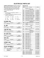
Page 57: ...B3080 2L008 SCREW B TIGHT M3X8 BIND HEAD GBHB3080 2L020 SCREW C TIGHT M3X6 E5610UD 0VM412937A 2L021 SCREW C TIGHT M3X6 E5610UD 0VM412937A 2L022 SCREW C TIGHT M3X6 E5610UD 0VM412937A 2L023 SCREW C TIGHT M3X6 E5610UD 0VM412937A 2L024 SCREW C TIGHT M3X6 E5610UD 0VM412937A 2L030 SCREW P TIGHT M3X8 BIND HEAD GBJP3080 2L031 SCREW P TIGHT M3X8 BIND HEAD GBJP3080 2L040 SCREW S TIGHT M3X10 E5610UD 0VM41293...

Page 58: ...P CERAMIC CAP 1608 F Z 0 1µF 25V CHD1EZ30F104 C2013 ELECTROLYTIC CAP 100µF 10V M H7 CEB101ENW025 C2016 CHIP CERAMIC CAP CH J 27pF 50V CHD1JJ3CH270 C2017 CHIP CERAMIC CAP CH J 27pF 50V CHD1JJ3CH270 C2018 CHIP CERAMIC CAP 1608 CH J 1000pF 50V CHD1JJ3CH102 CONNECTORS CN2005 FFC CONNECTOR 22P IMSA 9615S 22C PP A JC96J22ER009 CN2006 CONNECTOR PRINT OSU S3B PH K S LF SN J3PHC03JG030 CN2007 CONNECTOR PRI...

Page 59: ... POWER SW CBA Consists of the following SWITCH SW2007 TACT SWITCH SKHHALA010 SST0110AL005 MISCELLANEOUS WX2003 WIRE ASSEMBLY FRONT PWSW 3P WX1E1U00 002 WX1E1U00 002 Ref No Description Part No WiFi CBA Consists of the following 1VSA26844 CONNECTORS CN2001 PH CONNECTOR SIDE 5P S5B PH K S LF SN J3PHC05JG030 CN2002 WIRELESS LAN MODULE WM5502 UWLMDLACM001 MISCELLANEOUS B31 CUSHION E5W00UD 1VM437739 Ref...

Page 60: ...n without the obligation to notify any person or organization of such changes with the design is a registered trademark of Funai Electric Co Ltd and may not be used in any way without the express written consent of Funai All other trademarks used herein remain the exclusive property of their respective owners Nothing contained in this manual should be construed as granting by implication or otherw...

Reviews: