background image

TABLE OF CONTENTS   


Page 

Service Manual 

. Mechanical and Dismantling Instructions…………........................3-1
. Software Upgrades 

..........................................

.............................

.

4-1

. Trouble Shooting Chart………………………………………………

.

5-1

. Wiring Diagram………………………………………..………..….….6-1 
. Electrical Diagrams and Print-layouts..….…………………....….…7-1     
. Set Mechanical Exploded view & Part list.…………………..….….8-1 

©Copyright 201

1

 Philips Consumer Electronics B.V. Eindhoven, The Netherlands 

All rights reserved. No part of this publication may be reproduced, stored in aretrieval system or 
transmitted, in any form or by any means, electronic, mechanical, photocopying, or otherwise 
without the prior permission of Philips. 

CLASS 1 

LASER PRODUCT

PHILIPS

GB

HTS

3201

/12

. DFU Instruction..............................................................................2-1

. Revision List..................................................................................9-1

Home Theater DVD Player

. Technical Specifications…………....………………………..............1-

3

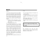
. Safety Instruction, Warning & Notes….……………………....….....1-

4

. Location of PCB BdsÿVersion Variation and Repair Scenario Matrix..........1-2

Published by 

RY&WL

  - 1

127

   BU AVM   Printed in The Netherlands   Subject to modification

3139 785 35

850

Version 1.

0

Service

Summary of Contents for HTS3201/12

Page 1: ...publication may be reproduced stored in aretrieval system or transmitted in any form or by any means electronic mechanical photocopying or otherwise without the prior permission of Philips CLASS 1 LASER PRODUCT PHILIPS GB HTS3201 12 DFU Instruction 2 1 Revision List 9 1 Home Theater DVD Player Technical Specifications 1 3 Safety Instruction Warning Notes 1 4 Location of PCB BdsÿVersion Variation a...

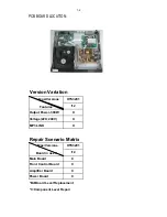
Page 2: ...ower 300W X Voltage 220 240V X MP3 LINK X Repair Scenario Matrix 12 Main Board C Front Control Board C Amplifier Board C Power Board C Bd Board Level Replacement C Component Level Repair Type Versions Board in used HTS3201 Type Versions Features HTS3201 ...

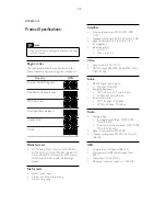
Page 3: ...nal to noise ratio FM 50 dB Frequency response FM 200 Hz 12 5 kHz 6 dB USB Compatibility Hi Speed USB 2 0 Class support USB Mass Storage Class MSC File system FAT16 FAT32 Maximum memory support 160 GB Note Specifications and design are subject to change without notice Region codes The type plate on the back or bottom of the home theater shows which regions it supports Media formats DVD Video DVD R ...

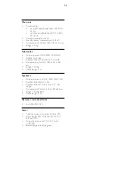
Page 4: ...peaker drivers 165 mm 6 5 woofer Dimensions WxHxD 195 x 265 x 265 mm Weight 3 20 kg Cable length 3 m Speakers Output power 2 x 75 W RMS 30 THD Speaker impedance 4 ohm Speaker drivers 1 x 63 5 mm 2 5 full range Dimensions WxHxD 84 5 x159 x 80mm Weight 0 35 kg each Cable length 3 m Remote control batteries 2 x AAA R03 1 5 V Laser Type Semiconductor laser GaAIAs CD Wave length 645 665 nm DVD 770 800 ...

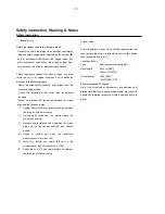
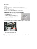
Page 5: ... wire between the two pins of the mains plug 2 Set the mains switch the on position keep the mains cord unplug 3 Measure the resistance value between the mains plug and the front panel controls and chassis bottom 4 Repair or correct unit when the resistance measurement is less than 1M 5 Verify this before you return the unit to the customer user ref UL standard no 1492 6 Switch the unit off and re...

Page 6: ...ch copper tracks and or components in this unshielded primary area when you service the player Service personnel must take precautions to prevent touching this area or components in this area A lighting stroke and a stripe marked printing on the printed wiring board indicate the primary side of the power supply Never replace modules or components while the unit is on 2 Laser The use of optical ins...

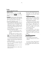
Page 7: ...WV J 5HSODFH WKH GHIHFWLYH ORDGHU ZLWK D QHZ ORDGHU 5HPRYH SDSHUFOLS IURP WKH ÀH IRLO DQG FRQQHFW LW WR WKH QHZ ORDGHU 5HPRYH VROGHU MRLQW RQ WKH 6 SURWHFWLRQ SRLQW 77 17 21 7KH ODVHU GLRGH RI WKLV ORDGHU LV SURWHFWHG DJDLQVW 6 E D VROGHU MRLQW ZKLFK VKRUWFLUFXLWV WKH ODVHUGLRGH WR JURXQG RU SURSHU IXQFWLRQDOLW RI WKH ORDGHU WKLV VROGHU MRLQW PXVW EH UHPRYH DIWHU FRQQHFWLRQ ORDGHU WR WKH VHW 2QO D...

Page 8: ...ch off un used equipment or reduce heat x Mix of lead free solder alloy parts with leaded solder alloy parts is possible but PHILIPS recommends strongly to avoid mixed solder alloy types leaded and lead free If one cannot avoid clean carefully the solder joint from old solder alloy and re solder with new solder alloy SAC305 x Use only original spare parts listed in the Service Manuals Not listed s...

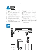
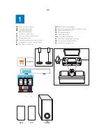
Page 9: ...zza NL Lees voordat u het product gaat gebruiken eerst alle bijbehorende veiligheidsinformatie NO Les all vedlagt sikkerhetsinformasjon før du bruker produktet PT Antes de utilizar o produto leia todas as informações de segurança que o acompanham SV Innan du använder produkten ska du läsa all tillhörande säkerhetsinformation TR Ürününüzü kullanmadan önce ilgili tüm güvenlik bilgilerini okuyun CS P...

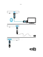
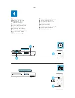
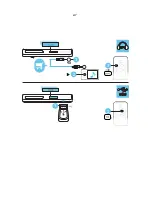
Page 10: ...casa FI Kotiteatterin liitännät FR Connecter les enceintes au Home Cinéma IT Collegamento del sistema HomeTheater NL Sluit de home cinema aan NO Koble til hjemmekinoanlegget PT Efectuar as ligações ao sistema de cinema em casa SV Anslut hemmabiosystemet TR Ev sinemasını baĚlayın CS Pŏipojte domácí kino HU A házimozi csatlakoztatása PL PodãĀczanie zestawu kina domowego RO Conectaŗi sistemul home th...

Page 11: ...HDMI IN 0 ANTENNA AC MAINS HDMI OUT 2 3 ...

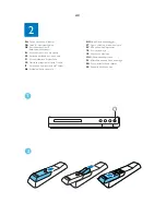
Page 12: ...eminen kotiteatteriin FR Mettre sous tension le Home Cinéma IT Accensione del sistema HomeTheater NL Schakel de home cinema in NO Slå på hjemmekinoanlegget PT Ligar o sistema de cinema em casa SV Sätt på hemmabiosystemet TR Ev sinemasını açın CS ZapnĖte domácí kino HU A házimozi bekapcsolása PL WãĀczanie zestawu kina domowego RO Porniŗi sistemul home theater SK Zapnutie domáceho kina 1 2 2 4 ...

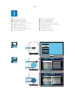
Page 13: ...Executar a configuração inicial SV Slutför förstagångsinställningen TR īlk kullanım öncesi kurulumunu tamamlayın CS DokonĈili jste nastavení pŏi prvním zapnutí HU Az elsʼn üzembe helyezés PL Pierwsza konfiguracja RO Realizaŗi prima configurare SK DokonĈenie prvého nastavenia HDMI TV HOME THEATER HOME THEATER 1 2 3 5 4 HQHUDO 6HWXS 26 DQJXDJH 6FUHHQ 6DYHU LVF RFN DV LQN 6HWXS LVSOD LP 6OHHS 7LPHU XWR 6...

Page 14: ...en FR Utiliser votre Home Cinéma IT Utilizzo del sistema HomeTheater NL Uw home cinema bedienen NO Bruke hjemmekinoanlegget 4 PT Utilizar o sistema de cinema em casa SV Använda hemmabiosystemet TR Ev sinema sisteminin kullanılması CS Použití domácího kina HU A házimozi használata PL Korzystanie z zestawu kina domowego RO Utilizaŗi sistemul home theater SK Používanie domáceho kina 3 2 1 1 2 2 6 ...

Page 15: ...3 MUSIC iLINK 1 2 2 1 2 7 ...

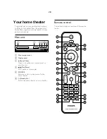
Page 16: ...b Display panel c Open Close Open or close the disc compartment or eject the disc d Play Pause Start pause or resume play e SOURCE Select an audio or video source for the home theater f Standby On Switch the home theater on or to standby Your home theater Remote control This section includes an overview of the remote control 1 2 3 4 5 6 7 8 20 9 10 11 12 13 14 15 16 17 18 19 21 22 23 24 2 8 ...

Page 17: ...reset radio station h Mute Mute or restore volume i VOL Increase or decrease volume j SOUND Select a sound mode k Numeric buttons Select an item to play l ANGLE Select video scenes recorded in different camera angels m REPEAT PROGRAM Select or turn off repeat mode In radio mode set a radio station n REPEAT A B Mark two points within a chapter or track to repeat play or turn off the repeat mode o C...

Page 18: ...r Figure 1 Figure 1 Step2 If it is necessary to dismantle Loader or Front Panel the Front door should be removed first Figure 2 Note Make sure to operate gently otherwise the guider would be damaged Figure 2 3 1 Please kindly note that dismantle the front door assembly carefully to avoid damage tray and the front door Detailed information please refer to the model set Sample Model HTS3531 12 ...

Page 19: ... refer to the model set 5 Figure 3 Step5 that connects the loader and the bottom cabinet Figure 5 Dismantle Loader disconnect the 3 connectors XP2 XP3 XP6 aiming in the below figure and remove 2 screws Figure 4 Figure 5 Dismantle Front Panel disconnect the connectors XP4 XP8 XP12 need release 2 snaps of Front Panel 2 snaps Dismantle Front Control Board remove 5 screws Figure 4 ...

Page 20: ...se refer to the model set Step6 Step7 Step8 Dismantle Amplifier Board remove screws Dismantle Main Board first disconnect 2 connectors XP1 XP11 and then remove 6 screws Figure 5 6 Dismantle Power Board disconnect the connectors XS703 and CN501 on Power Board then remove 5 screws Figure 5 6 Figure 5 6 4 ...

Page 21: ...6 Don t power off wait until the player reset automatically the whole upgrade process may need 2 minutes HTS will auto standby after complete upgrade B Read out the software versions to confirm upgrading Follow the steps shows below SETUP Preference Setup Version Info While it shows the dialog box we can see some information like below For example Upgrade file name HTSxxxx xx bin version xx xx xx ...

Page 22: ...o Yes Yes Yes Correct connection No Yes Replace U135 or VFD Check every supply voltage on Main Board whether normal or not XP1 PIN1 24V PIN3 12V PIN5 PIN6 5V Check voltage 24V 5V 12V on Power Board at CN502 position and Front Control Board HTS3201 XP2 PIN4 24V PIN5 12V PIN6 3 3V Check the power key HTS3201 S608 open closed key HTS3201 K138 source key HTS3201 K135 on Touch Board whether work normal...

Page 23: ...e connection XP2 on Front Control Board and XP12 on MAIN BOARD Yes Replace U135 on Front Control Board No Yes Replace Front Control Board Check voltage 3 3V on Front Control Board HTS3201 XP2 PIN9 and voltage 5V on U135 PIN14 Check Front Control Board signals U135 PIN10 PIN11 PIN12 ...

Page 24: ... work Go No Replace the battery for remote control Yes Check the 3 3V net on Front Control Board HTS3201 XP2 No Yes Replace IR601 Check battery of remote control whether exhausted or not Check power supply of IR601 on Front Control Board whether normal or not HTS3201 XP2 PIN9 3 3V ...

Page 25: ...voltage 33 V whether normal or not at XS703 on Amplifier Board Check the 24pin FFC connection XP11 on Main Board and XP702 on Amplifier Board whether right or not between Main Board and Amplifier Board Check the control signal whether right or not at the U1 PIN59 PIN60 PIN63 on Main Board and the signal at the XP11 PIN9 PIN10 PIN22 Check XP11 pin 14 16 3 3V on Main Board whether normal or not ...

Page 26: ... Trouble shooting Chart No video output No video output Go Add L6 R433 on Main Board Yes No No Replace Main Board Check L6 R433 whether right on Main Board Check the video signal whether right at U1 PIN139 ...

Page 27: ...k door Can t read disc or can t open the disk door Go Check XP1 on Main Board No Yes Fix 24pin 6pin and 5pin cable No Replace Loader Yes Check loader whether work normally or not Check 24pin 6pin and 5pin cable from Main Board to Loader whether connect right or not ...

Page 28: ...ge the Tuner module No Yes Yes No Yes Replace Main Board Check Main Board U1 power supply circuit Check voltage 3 3V at Tuner module TUN1 pin5 whether right or not Check Tuner module pin7 pin8 pin9 I2S output whether normal or not Check voltage at Q6 3 3V on Main Board whether normal or not Check the U1 PIN53 PIN54 I2C output on Main Board whether normal or not ...

Page 29: ...ace U5 74HC4052 Check Main Board U1 No Yes Check Main Board U1 power supply and out circuit No Yes Check voltage at U12 PIN8 12V on Main Board whether normal or not Check Main Board U5 PIN2 PIN15 signal input whether right or not Check voltage at U5 74HC4052 PIN16 6V on Main Board Whether normal or not Check U5 74HC4052 whether broken Or not ...

Page 30: ...52 Check Main Board U1 No Yes Check Main Board U1 power supply and out circuit No Yes HTS3201 Check signal at XS605 PIN3 MP3_R PIN1 MP3_L ON front board whether normal or not Check Main Board U5 74HC4052 PIN4 PIN11 L R signal input whether right or not Check U5 74HC4052 whether broken Or not Check voltage at U5 74HC4052 PIN16 VDD 6V on Main Board Whether normal or not ...

Page 31: ... does not work OPTICAL in does not work Go No Refer to Power Board CN502 Yes Check Main Board C106 No Replace U1 Yes Check voltage at P2 PIN1 5V on Main Board whether normal or not Check Main Board P2 PIN3 signal input whether right or not ...

Page 32: ...control 6PIN 6PIN 1 6 10pin 2 5 CN501 CN531 AMP AMP STA516B Power limit control circuit 1 VFD DISPLAY PT6312 ASA 8829 S76RFXP2 DVD LOADER 4558 AK5358 4ohm 8ohm MIC MP3 IN XP11 XP1 XP6 XP2 XP3 XP4 XP12 XP2 XS604 XS605 XP701 XS703 CN502 33V PGND PGND PGND 33V 33V F F T T D RF A B F Vc Vref C CD DVD SW GND PD Vcc E NC VR CD VR DVD CD LD MD HFM NC DVD LD GND LD GND MIC_DET GND 24V 12V 3 3V SCK SDA STB...

Page 33: ...4 R3 0 R3 0 C610 100pF 50V NP0 C610 100pF 50V NP0 CE1 10uF 16V CE1 10uF 16V Q138 NPN_3DG3904M Q138 NPN_3DG3904M 47uF 16V CE606 47uF 16V CE606 Q136 NPN_3DG3904M Q136 NPN_3DG3904M FB609 500 600mA FB609 500 600mA R635 100 R635 100 R146 10K R146 10K CE608 220uF 16V CE608 220uF 16V ESD1 PRTR5V0U2X ESD1 PRTR5V0U2X 1 2 3 4 R5 100 R5 100 K136 K136 C607 1000pF 50V X7R C607 1000pF 50V X7R C626 47pF 50V NP0 ...

Page 34: ...703 22uH 3 3A L703 22uH 3 3A 1 2 TP30 TP30 C734 0 1uF 50V X7R C734 0 1uF 50V X7R R769 30K R769 30K C735 0 1uF 50V X7R C735 0 1uF 50V X7R L705 22uH 3 3A L705 22uH 3 3A 1 2 220uF 35V CE724 220uF 35V CE724 C768 0 1uF 50V X7R C768 0 1uF 50V X7R C794 0 22uF 50V X7R C794 0 22uF 50V X7R XS703 6PIN 2 5mm XS703 6PIN 2 5mm 1 1 2 2 3 3 4 4 5 5 6 6 C787 0 1uF 25V Y5V C787 0 1uF 25V Y5V TP27 TP27 220uF 35V CE7...

Page 35: ...ND 45 NC 46 OUT2B 47 OUT2A 48 OUT1B 49 OUT1A 50 EPAD 51 VDD 52 GND 53 NC 54 BICKO 55 LRCKO 56 SDI_12 57 SDO_34 58 VDD 59 GND 60 NC 61 SDIO_56 62 SDIO_78 63 PDWN 64 C727 0 1uF 25V Y5V C727 0 1uF 25V Y5V C731 0 1uF 25V Y5V C731 0 1uF 25V Y5V C730 1200pF 50V X7R C730 1200pF 50V X7R TP55 TP55 C717 0 1uF 25V Y5V C717 0 1uF 25V Y5V R703 33 R703 33 R767 1K R767 1K TP56 TP56 C732 47pF 50V NP0 C732 47pF 50...

Page 36: ...00VAC R537 2M R537 2M JP506 Jumper JP506 Jumper 1000uF 16V CE511 1000uF 16V CE511 L503 3 3uH 3A L503 3 3uH 3A C535 0 1uF 50V X7R C535 0 1uF 50V X7R C534 0 1uF 50V X7R C534 0 1uF 50V X7R D506 FR107 1A 1000V D506 FR107 1A 1000V R528 150K R528 150K D507 1N4148 D507 1N4148 C540 0 1uF 50V X7R C540 0 1uF 50V X7R T531 PQ3230 T531 PQ3230 A8 8 A10 10 D 3 P GND 5 FB 6 VDD 1 N C 2 A12 12 A9 9 D533 MUR2020FCT...

Page 37: ... Y5V C102 0 1uF 25V Y5V R20 22K R20 22K C6 0 1uF 25V Y5V C6 0 1uF 25V Y5V TP1 TP1 R14 4 7K R14 4 7K C9 0 1uF 25V Y5V C9 0 1uF 25V Y5V R5 1 3K R5 1 3K R4 22K R4 22K Q8 NPN_3DG3904M Q8 NPN_3DG3904M C3 1uF 50V Y5V C3 1uF 50V Y5V R89 0 R89 0 R1 0 NC R1 0 NC R18 15K 1 R18 15K 1 220uF 16V CE7 220uF 16V CE7 FB1 300 2A FB1 300 2A C7 0 1uF 25V Y5V C7 0 1uF 25V Y5V Q9 NPN_3DG3904M Q9 NPN_3DG3904M Q3 NPN_3DG...

Page 38: ... 1 2 2 3 3 4 4 5 5 6 6 R55 10K R55 10K C30 1uF 50V Y5V C30 1uF 50V Y5V R27 10K R27 10K R64 0 R64 0 C46 0 1uF 25V Y5V C46 0 1uF 25V Y5V C49 0 1uF 25V Y5V C49 0 1uF 25V Y5V FB14 500 500mA FB14 500 500mA C27 0 1uF 25V Y5V C27 0 1uF 25V Y5V C14 0 1uF 25V Y5V C14 0 1uF 25V Y5V CE11 100uF 25V CE11 100uF 25V C47 0 1uF 25V Y5V C47 0 1uF 25V Y5V CE19 4 7uF 10V Y5V CE19 4 7uF 10V Y5V FB15 500 500mA FB15 500...

Page 39: ...V R78 10K R78 10K TP4 TP4 C66 0 1uF 25V Y5V C66 0 1uF 25V Y5V C60 0 1uF 25V Y5V C60 0 1uF 25V Y5V R76 10K R76 10K R71 33 R71 33 100uF 25V CE26 100uF 25V CE26 100uF 25V CE24 100uF 25V CE24 XP6 5PIN 2 0mm XP6 5PIN 2 0mm 1 1 2 2 3 3 4 4 5 5 C62 0 1uF 50V Y5V C62 0 1uF 50V Y5V C71 0 1uF 25V Y5V C71 0 1uF 25V Y5V U2 SDRAM_64Mb_M12L64164A 7T U2 SDRAM_64Mb_M12L64164A 7T VCC 1 DQ0 2 DQ1 4 VSSQ 12 DQ2 5 DQ...

Page 40: ...SD_PGB101 D4 PESD_PGB101 C170 1uF 50V Y5V C170 1uF 50V Y5V C118 100pF 50V NP0 C118 100pF 50V NP0 C168 1uF 50V Y5V C168 1uF 50V Y5V U5 74HC4052 U5 74HC4052 Y0 1 Y2 2 Y 3 Y3 4 Y1 5 EN 6 VEE 7 GND 8 B 9 A 10 X3 11 X0 12 X 13 X1 14 X2 15 VCC 16 R176 150K NC R176 150K NC R112 4 7K R112 4 7K R113 100 NC R113 100 NC R642 100K R642 100K C164 1uF 50V Y5V C164 1uF 50V Y5V CE608 47uF 16V CE608 47uF 16V R98 1...

Page 41: ...2012H 900 2P 1 3 2 4 D7 PESD_PGB101 D7 PESD_PGB101 R133 1 5K R133 1 5K P4 HDMI JACK P4 HDMI JACK 1 2 3 4 5 6 7 8 9 10 11 12 13 14 15 16 17 18 19 22 21 20 23 C93 100pF 50V NP0 C93 R143 91 R143 91 R132 75 R132 75 RCA 3h P3 RCA 3h P3 1 2 3 4 5 U603 SGM8051 U603 SGM8051 Vout 1 Vs 2 IN 3 IN 4 Vs 5 R149 1 5K R149 1 5K L8 ACM2012H 900 2P L8 ACM2012H 900 2P 1 3 2 4 Q25 NPN_3DG3904M Q25 NPN_3DG3904M R657 1...

Page 42: ...2 3 3 4 4 5 5 6 6 7 7 8 8 9 9 10 10 11 11 12 12 13 13 14 14 15 15 16 16 17 17 18 18 19 19 20 20 21 21 22 22 23 23 24 24 GND 25 GND 26 XP12 14PIN 1 0mm XP12 14PIN 1 0mm 1 1 2 2 3 3 4 4 5 5 6 6 7 7 8 8 9 9 10 10 11 11 12 12 13 13 14 14 C109 0 1uF NC C109 0 1uF NC R169 100 R169 100 C122 27pF 50V NP0 C122 27pF 50V NP0 R190 0 R190 0 C108 0 1uF NC C108 0 1uF NC TU1 TUNER_13P_A TU1 TUNER_13P_A LOUT 8 GND...

Page 43: ...7 11 Front Control Board Print layout top side 7 11 ...

Page 44: ...7 12 Amplifier Board Print layout top side 7 12 ...

Page 45: ...7 13 7 13 Amplifier Board Print layout bottom side ...

Page 46: ...7 14 Power Supply Print layout top side 7 14 ...

Page 47: ...7 15 Power Supply Print layout bottom side 7 15 ...

Page 48: ...Main Board Print layout top side 7 16 7 15 7 16 ...

Page 49: ...Main Board Print layout bottom side 7 17 7 17 ...

Page 50: ...8 1 EXPLODED VIEW FOR HTS3201 12 This is general mechanical exploded view Please refer to the model set for the detailed information ASSY1 includes components 15 16 17 19 24 ...

Page 51: ...REVISION LIST Version 1 0 9 1 Initial release for HTS3201 12 ...

Reviews: