3 - 2
3 - 2
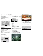
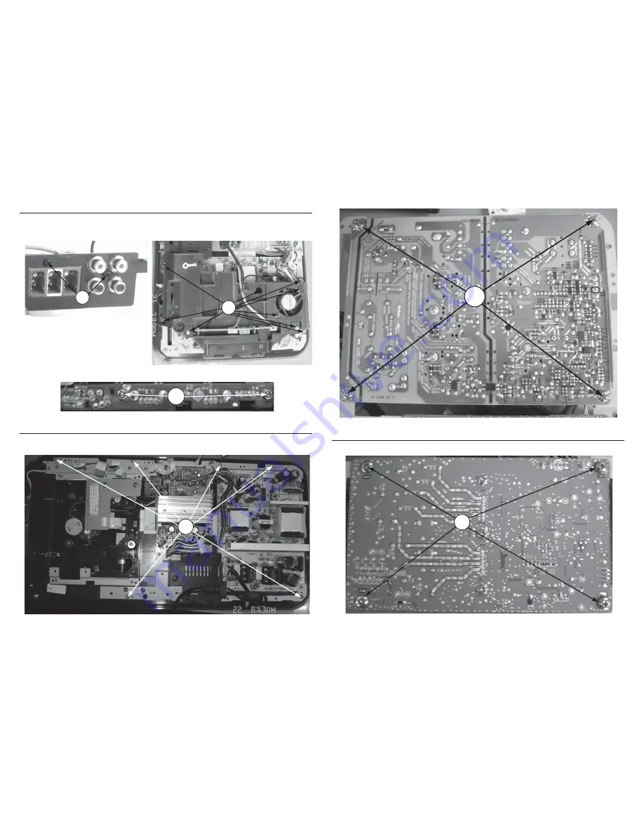
Dismantling of the USB+AUX PCB
1) Loosen 2 screws “F” at the main PCB bracket to remove AUX PCB as shown in fi gure 7.
2) Loosen 9 screws “G” to remove DVD fan bracket&fan&USB bracket as shown in fi gure 8.
3) Loosen 2 screws “H” on the USB PCB to remove it as shown in fi gure 9.
Figure 7
F
H
Figure 9
G
Figure 8
Dismantling of the Power PCB
1) Loosen 6 screws “I” at the power PCB bracket as shown in fi gure 10.
2) Loosen 4 screws “J” on the power PCB bottom to remove power PCB as shown in fi gure 11.
I
Figure 10
J
Figure 11
Dismantling of the AMP PCB
1) Loosen 4 screws “K” on the AMP PCB bottom to remove AMP PCB as shown in fi gure 12.
K
Figure 12
Summary of Contents for HTS5200
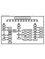
Page 9: ...2 2 2 2 REPAIR INSTRUCTIONS One ...
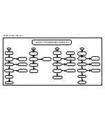
Page 10: ...2 3 2 3 REPAIR INSTRUCTIONS Two ...
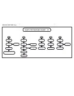
Page 11: ...2 4 2 4 REPAIR INSTRUCTIONS Three ...
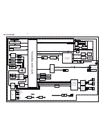
Page 15: ...4 1 4 1 BLOCK DIAGRAM ...
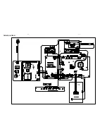
Page 16: ...4 2 4 2 WIRING DIAGRAM V3 V4 V1 V2 ...
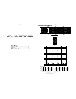
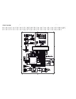
Page 33: ...9 1 9 1 TOUCH BOARD TABLE OF CONTENTS Circuit Diagram 9 2 PCB Layout Top View Bottom View 9 3 ...
Page 37: ...11 1 REVISION LIST Version 1 0 Initial release Version 1 1 Update chapter 1 2 ...


